Reviews
Automobile
1913 Ford Model T
by John Kaylor
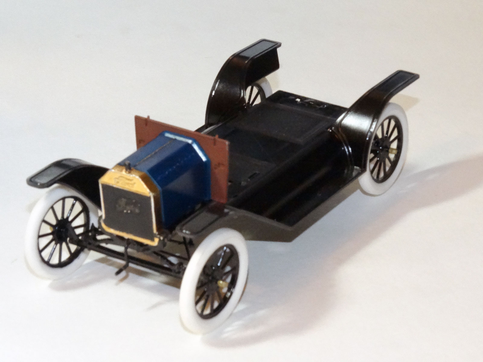
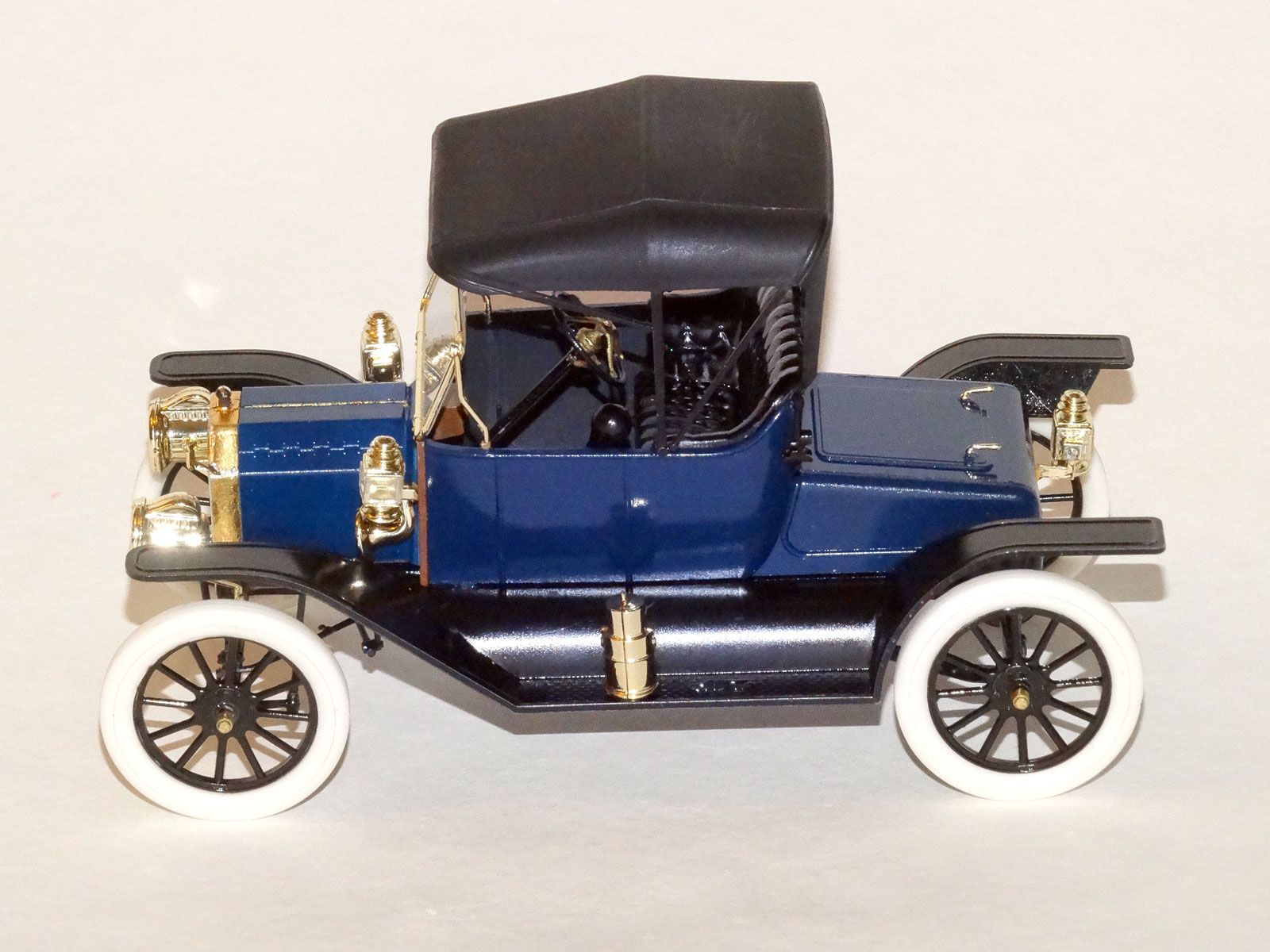
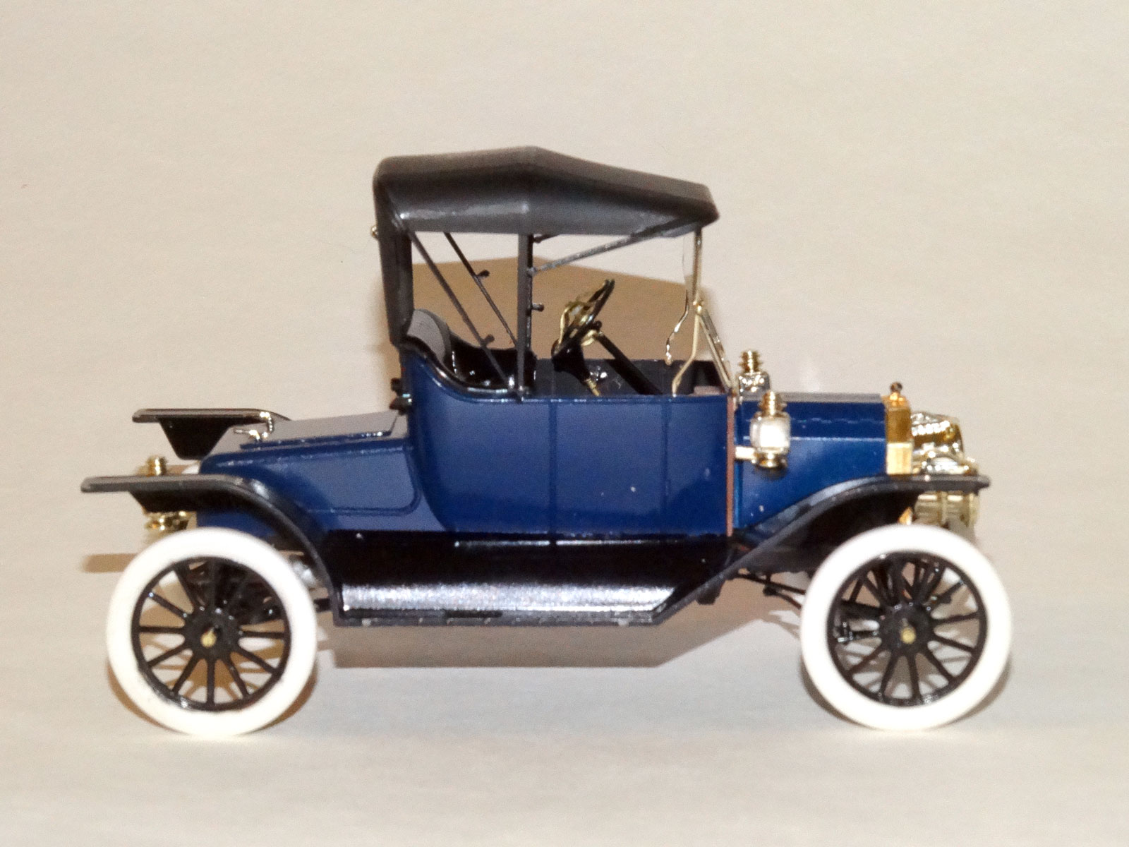
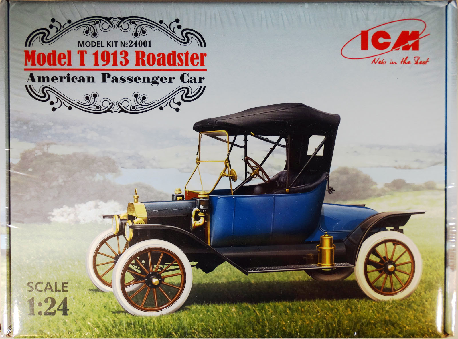 Model: 1913 Ford Model T Roadster
Reviewed by: John Kaylor, IPMS # 48733
Scale: 1/24
Company: ICM
Price: $59.99
Product/Stock #: 24001
Website: ICM
Product Web Page: View
Product provided by: ICM
ICM has produced a little gem – an extremely authentic, well-engineered, gem of a model.
First of all to introduce myself a bit. I have been palling around with my wife and her parents around for the past twenty-eight years, and her family has owned a Ford Model T since my wife was a young child. Between our two families, we own three Model Ts, one of which a 1914 Touring, not unlike this 1913 Roadster. My father-in-law, Jim, restored a T in the early 1970s, and Jim and I restored my wife’s 1926 T in the 1990s. I bring all of this up to illustrate that we’ve spent enough time under these old rigs to know where not to step after one has been parked for a while.
Background
The Model T was the first mass-produced automobile. In 1913 over 170,000 Model Ts were produced; an average of one Model T rolled off the assembly line every 185 seconds. For production to maintain levels that high, everything had to be done at breakneck speed, including painting.
The Model T assembly line was like a railroad track, and each T chassis rode on a sort of tram. One thing was done at each station along the track.
The same sort of thing was done with the body. Just before the last stage of assembly, the body of the T was brought into a room with a steel grate floor. A Ford worker then took a hose that resembled a garden hose and “flowed” a paint called “Japan Enamel” onto the body. Japan Enamel would tend to not drip, rather it would tend to flow down the body and the excess would drip down through the grating, where it would then be directed back into the paint hose. Lastly in the assembly line, the engine was dropped into the car and the body was put on top of the chassis.
As a result of all of this, the paint on the original vehicles was not perfect. It had drips. It had uneven spots. It probably even had spots where there was little or no paint. When you are restoring a Model T, the public assumes that you will spend a small fortune to put a perfect paint job on the car, not realizing that this would be an incredible over-restoration.
A perfect paintjob would be overdone, but no one is going to understand a scale model’s paintjob that has any kind of drip on it, in spite of the facts. And as good as one might be at modeling, creating realistic 1:24 drips might be a trick, so I guess I’m conceding that in spite of the way things were, a model might get judged poorly if a it was “completely authentic” with this regard.
The famous expression about Model Ts from 1914 on was, “you can have it any color as long as it’s black.” Through 1913, you still had a choice of color for the body. The official exterior colors for the Model T off the factory line apparently were: red, green, blue, and of course black.
The undercarriage of the Model T*, however, was always black. Ford build the “business end” of his cars all the same, and it was only when you were talking body style – touring, roadster, sedan, coupe, delivery, town car, etc. – that there were any differences between models. (* I’m ignoring the 1 Ton Truck chassis, because the facts inconveniently interfere with the narrative. Hey, this could be the start of a career as a politician!)
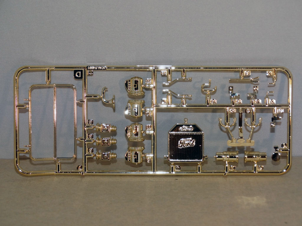
The kit contains: Three light gray sprues, two of which, the A and B sprues, are joined A light gray sprue for the wood wheels A brass-plated sprue A clear sprue
- Three light gray sprues, two of which, the A and B sprues, are joined
- A light gray sprue for the wood wheels
- A brass-plated sprue
- A clear sprue
- Push the right (throttle) lever on the steering column up to a slow the engine down
- Push forward slowly on the left (clutch) foot pedal until the transmission is in neutral
- Release the catch on the hand brake and push all the way forward so the transmission is in high – but remember you have your foot on the clutch, so you are still in neutral
- Slowly push the clutch pedal forward until the transmission engages in low gear while at the same time pulling down on the throttle lever on the steering column, giving the engine more gas and increasing speed
- Then when you are going about as fast as you can in low (10-15 mph), push the throttle up to slow the engine while at the same time letting your foot back completely off of the clutch pedal (and into high gear via the brake lever), and then slowly bring down the throttle to build speed
I opened the ICM box and scoured the model, determined to find any minute flaws in the kit. I found just a few issues. Everything else about the car is as close to perfect as I could possibly expect any company to produce. This kit is BEAUTIFUL.
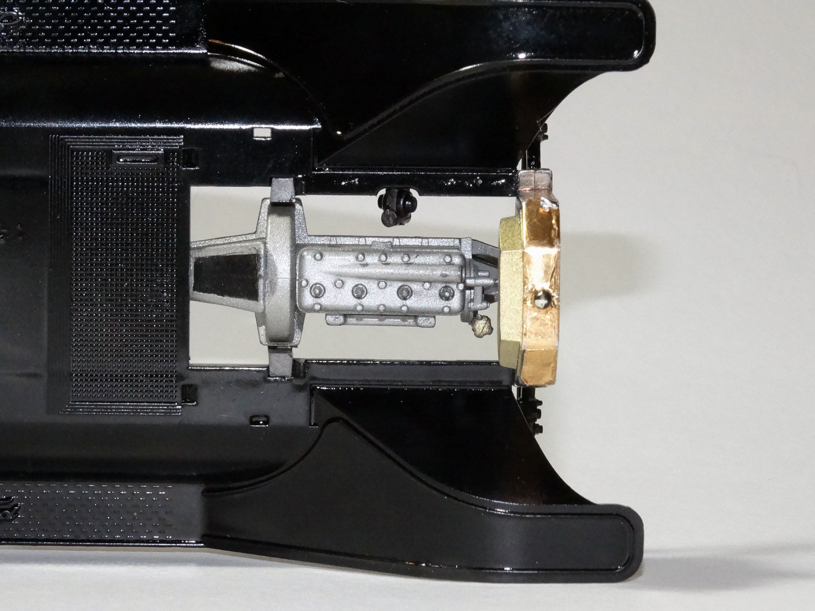
One tiny “flaw” is that on a real Model T, the top of the transmission (known to T owners as the “hog’s head”) has an access panel, about 1/8th inch thick, six inches wide at the top, and about four inches wide at the bottom. (For an example, you can go to http://www.snydersantiqueauto.com/transmission-door) This plate is missing on the kit’s transmission, and there is no direction on painting indicating that one should paint that portion of the hogshead black. But this is a trifle. You aren’t even going to see the transmission with the floorboards in place, and I don’t grade the kit down in the least because of its omission.
Another small thing is that there are no latches that hold down the hood. Forgivable – these would be tiny spring-loaded brass pieces that kind of get blocked from view by the fender, so it’s not a crucial thing to have missed.
The timer, which looks something like a distributor cap, and the linkage from the spark advance/retard lever are not reproduced - also forgivable for how incredibly small they would be, and the amount of engineering required for something that goes up in front of the engine where no one is going to see, and no one is going to miss it unless they know what they are looking for.
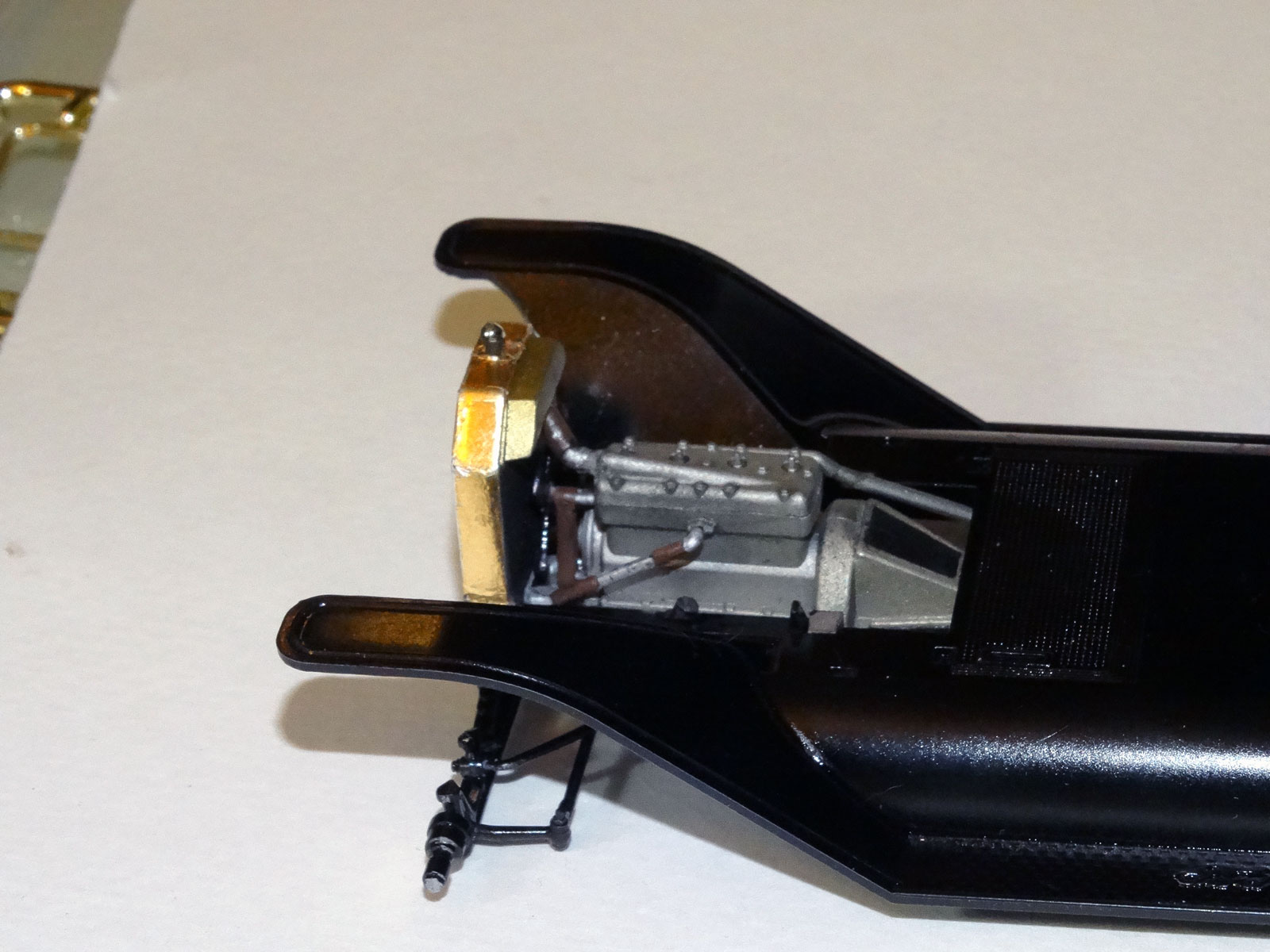
The last omission I can’t understand at all. After all of the engineering involved in this kit, it does not include a separate, distinct frame. It has a “sort of” frame that is cast into the bottom of the body. I’ve read other’s reviews that look at this as not a big deal because it is one thing fewer to assembled crooked, but I don’t see it that way at all. In my opinion, the frame could have been a separate structure, and you could have had a rolling chassis without having any portion of the body installed.
It seems to me that if there was ever a desire to release another of the body styles for the 1913 (of which there were at least six other options) that they made their lives trickier by leaving out the frame. But this is the only demerit I will give this model – it is truly incredible.
The parts all have a very high-level of detail, and the sprues are all very carefully laid out (and the part numbers are in numerical sequence – IMAGINE THAT!). There are many places with small ejector pin marks, and a few that would have gone unnoticed if they had merely been placed on the opposite side of the part, but generally these are raised features instead of pits, so they are easy enough to take off with a knife.
One of the places that impressed me most with regard to surface detail was the steering column. The steering column assembly has the small shafts on either side of the steering rod for the spark advance lever (on the left) and the throttle lever (on the right). The steering wheel quadrant is the piece of metal that the spark advance and throttle levers “rest” on, so that they don’t change position. The quadrant is highly-detailed. To me this is one of the most impressive areas of the model.
I’m not sure how to cut the steering wheel spider off of the sprue without damaging it. I seriously tried twice with two different kits, and ended up breaking the thing, and not being able to clean the casting reservoir off of the part. Because my parts were a little on the fragile side, my steering wheel looks funny because the spider is glued on top of the steering wheel, instead of the steering wheel sitting on top of the spider.
The spark advance and throttle levers are very tiny, and tricky to put in. But the instructions have the orientation of the levers exactly correct in their diagram in step 43. For a Model T that has been turned off, both levers should be up all the way (approximately 90 degrees to the floor.) A person not setting the levers that way when leaving the car was begging for a broken arm when they came back to crank the car back to life. If the spark (distributor) advance lever is not in almost full retard when you crank a Model T’s engine, the engine could kick-back, and the crank would go back toward your arm, handily snapping it as the engine sputters to a stop.
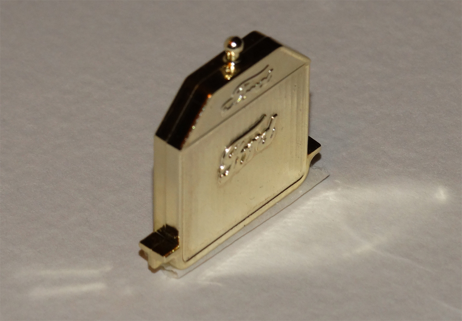
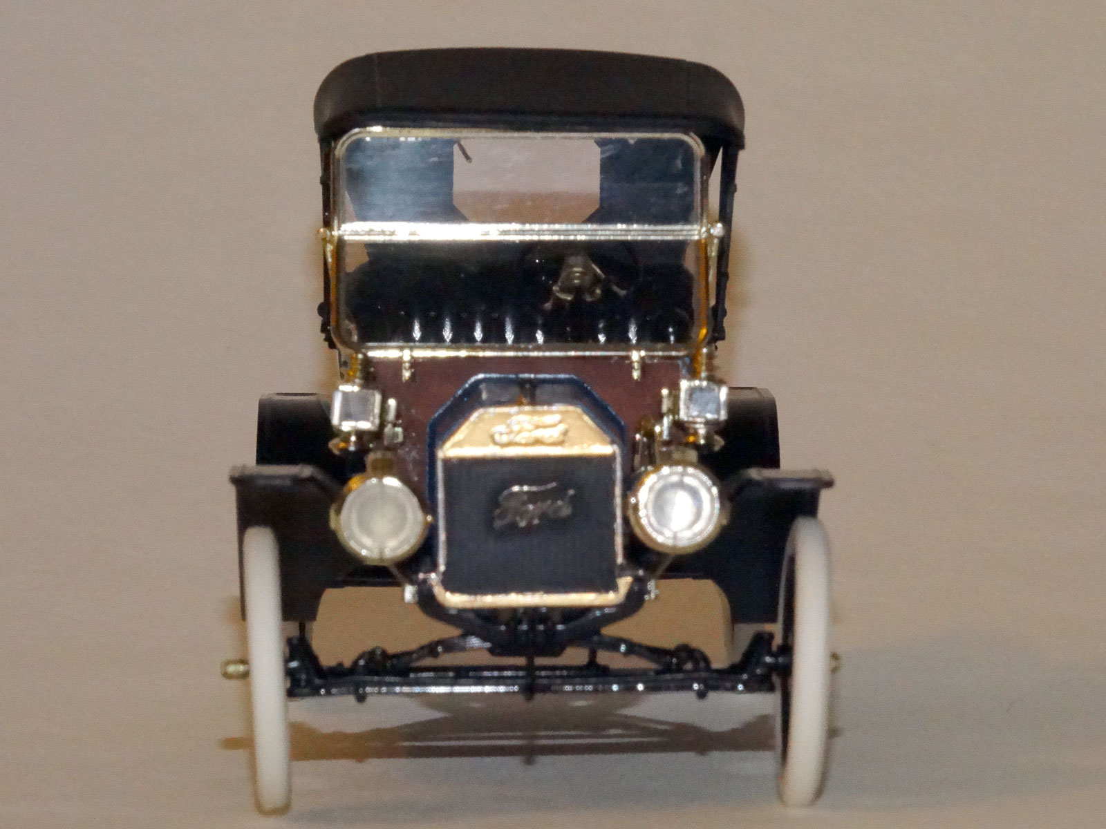
The brass parts are very nice, however, the radiator shell had terrible seam lines along the sides and top (see picture below), so I had to sand the edges, and had to order some gold BareMetal Foil to cover the radiator. (It was my first time using the BareMetal, and the seams at the top around the neck of the radiator are just a mess. I will probably make another stab at fixing the radiator, but if that doesn’t work out better, I might just try painting it with brass enamel.)
When I realized that all my messing around with the radiator shell was getting me nowhere, I contacted ICM through their web site and asked if they could send me a new radiator. Their customer support is very good, and within a relatively short period of time (much shorter than it takes to get a response out of Revell, for instance), they delivered a new part to me on their dime. Unfortunately I was already behind with my review kit, and because for whatever reason you can’t make much progress until after the radiator was put in place, I had already glued the original in place and wasn’t about to replace it.
The replacement part that I was sent did look better, but it would still have required removing a seam that I really don’t see an excuse for. The radiator shell of a Model T was smooth as a baby’s butt. Except, that is, if it was in the possession of an old car nut, in which case it would be smoother than a baby’s butt, because the owner spends all of his free time polishing the brass to make it shine… and he probably has never touched his own offspring’s posterior because he is too busy with the brass.
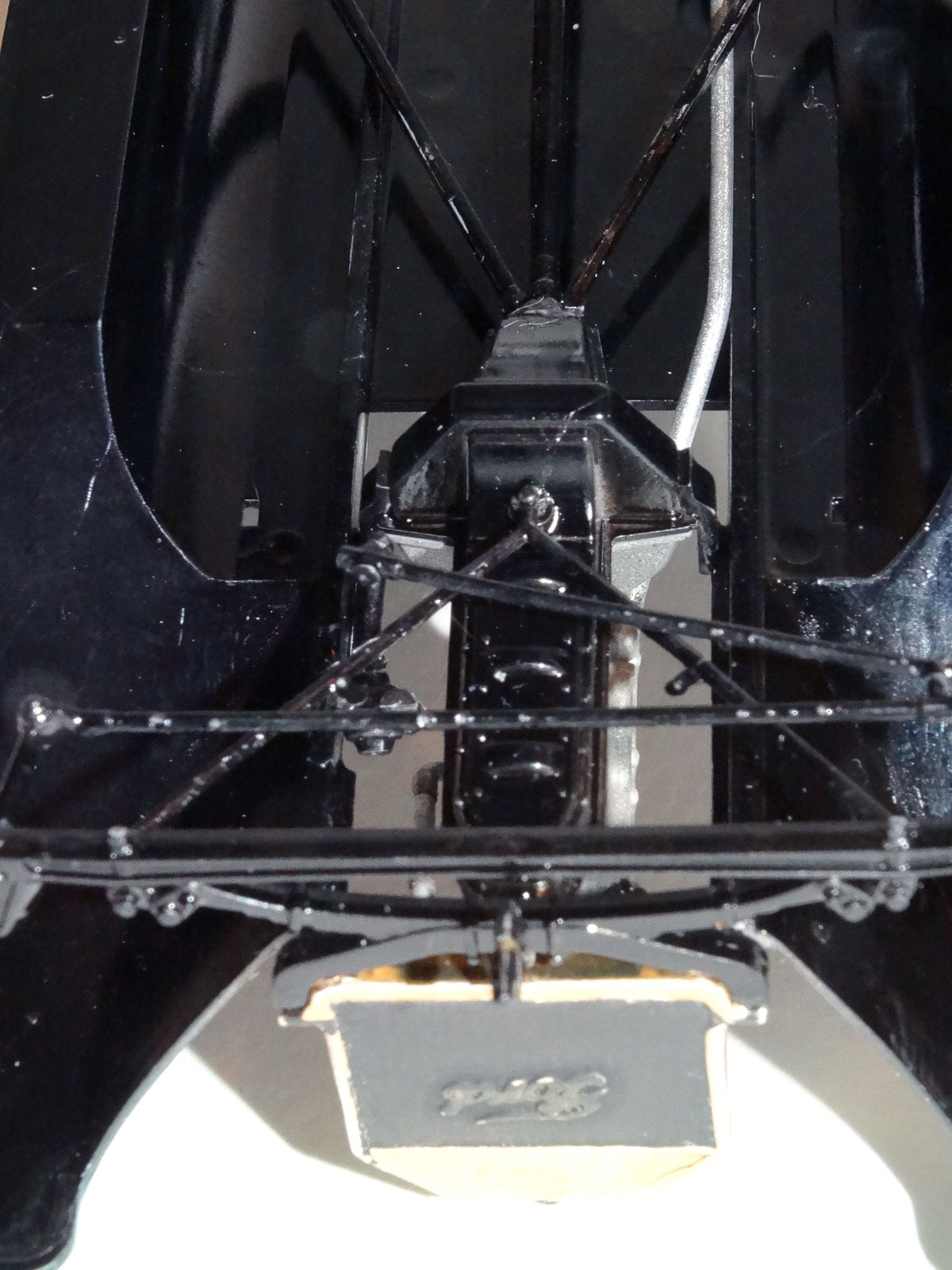
The best approach to the assembly of the ICM 1913 Ford Model T Roadster is to build the complete undercarriage, and then paint it all gloss black – no pre-painting, just build and black. My armor buddies would be proud.
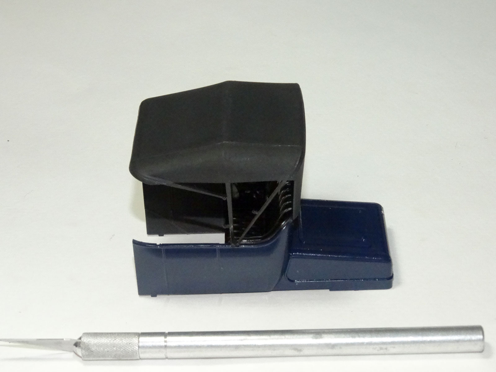
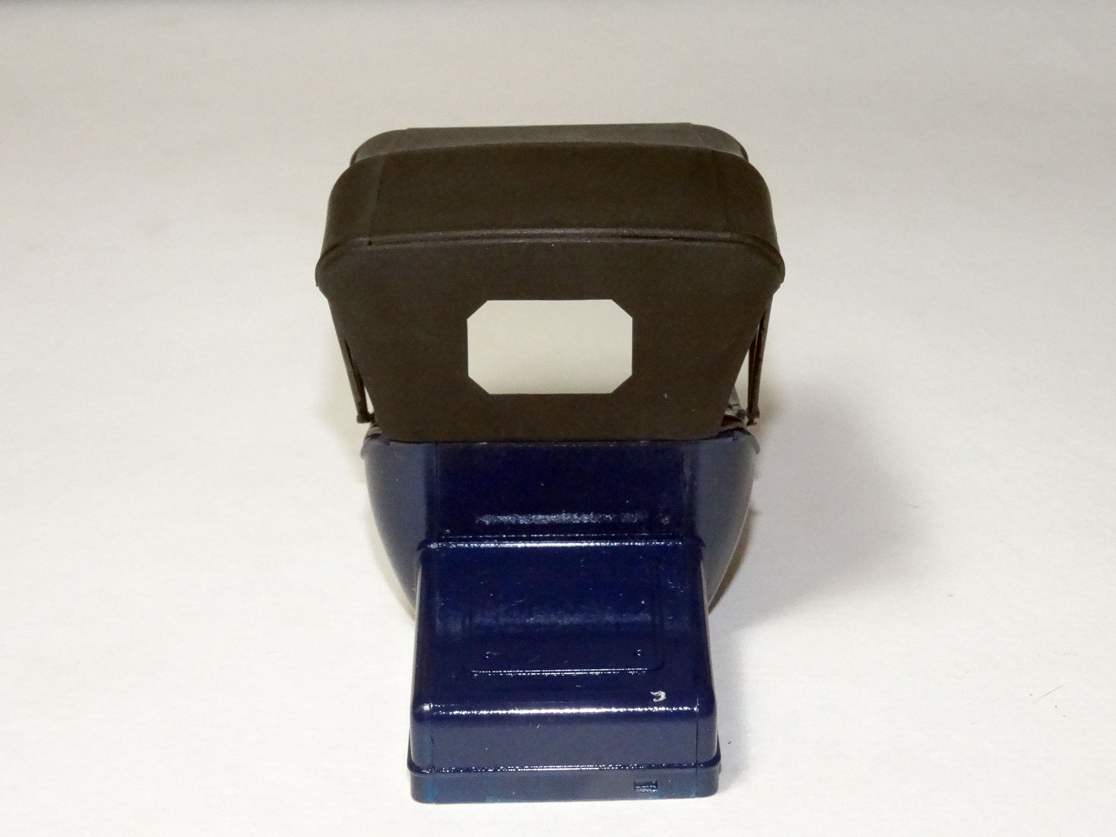
The body should be painted prior to adhering it to the frame. It’s a pretty simple little body, comprised of two sides, a back, and the “turtledeck”, or trunk of the car. (It was not until the Model A in 1930 that the trunk was big enough to be used as a “rumbleseat”, although many people did put a seat on top of the Model T trunk which was called a “mother-in-law seat”, ostensibly because the mother-in-law could sit there when a couple was on a date to chaperone.) Also to be painted body-color is the Hood Former, both halves of the hood, the hood hinge, and the front of the seat.
I can’t infer what the instructions are trying to tell you to paint the interior: if they are trying to tell you to paint the interior the exterior color, or if they are just telling you to paint the interior of the front door the exterior color. In either case they would be wrong, as the Model T had a Masonite-type material for the interiors which were always black.
So the interior of the body should be painted flat or semi-gloss black, or at least a very dark grey.
The instructions indicate that the spokes of the wheels should be painted a light brown color. That is actually incorrect; the spokes and “fellows” (the wood between the spokes on the outside of the wheel) should be black like the rest of the chassis.
The instructions also say to paint the firewall light brown. The 1913’s firewall was actually cherry-wood colored, so the actual color should be a red-brown. Don’t look at mine for a guide, because I didn’t get it where I wanted it to be.
Assembly starts with building the engine and transmission, then attaching the axles and driveline to the lower-body/frame part.
In step 11 the brass forks that hold the headlights are installed. You should hold off on this until after painting the undercarriage upon completion of step 22.
In step 12, the engine is added. I would BluTack the engine in place for this step rather than using cement, and skip step 13, where you add the radiator hoses, until after the engine is put in place for good following chassis painting.
Follow steps 14 through 16, which join the torque-tube (drive shaft) and differential together, glue the spring/rear-axle assembly onto the differential. Glue this assembly into place, making sure not to glue the front of the torque-tube to the engine at this point. Just use the engine to provide the angle at which the rear-end assembly needs to be in order for the torque tube to meet up with the engine appropriately.
Complete the undercarriage assembly by skipping to steps 20, where you glue in the wishbone and tie rod, and 21, where you add the radius rods and Pitman arm.
Now it is time to remove the engine and paint the entire undercarriage gloss black.
When the undercarriage is dry, retrace your steps and do the things that were put off until after painting the chassis. First put the brass forks that hold the headlights on, from step 11, glue the engine in place, as per step 12, and glue the radiator hoses in place, as in step 13.
Move to step 18 to add the exhaust manifold and tailpipe/muffler assembly. This is a little trickier than adding it before the radius rods are in place, but with some patience, you will get this up to meet the starboard side of the engine.
Step 19 puts on the brackets that hold the exhaust manifold in place. Wow. Those are tiny. And I could only find three of the four holes that they go into. Gulp. So I held off putting these little babies in place until I get brave, cover my entire working area with a white bed sheet, and get a really nice set of tweezers.
The only way around this would be possibly snipping the back part of the brackets that go into the engine block, and gluing these little parts in place directly on the exhaust manifold. Henry Ford doesn’t need to know that these T-shaped parts aren’t actually holding your manifold to the engine. I suppose ICM could have faked it and cast the exhaust manifold with these in place.
The tires are silicon? Latex? …something…. Anyhow, having little experience with these, I just glued them onto the wheel rims with a little CA glue. In retrospect, I should have used something more along the lines of Gator Glue or something, but it worked. The white tires are really snappy looking! If your adhesive smears the paint onto your white tires, wait until it dries and flake the adhesive off of the face of the tires with a hobby knife, rather than possibly introducing smudges on the pretty white tires.
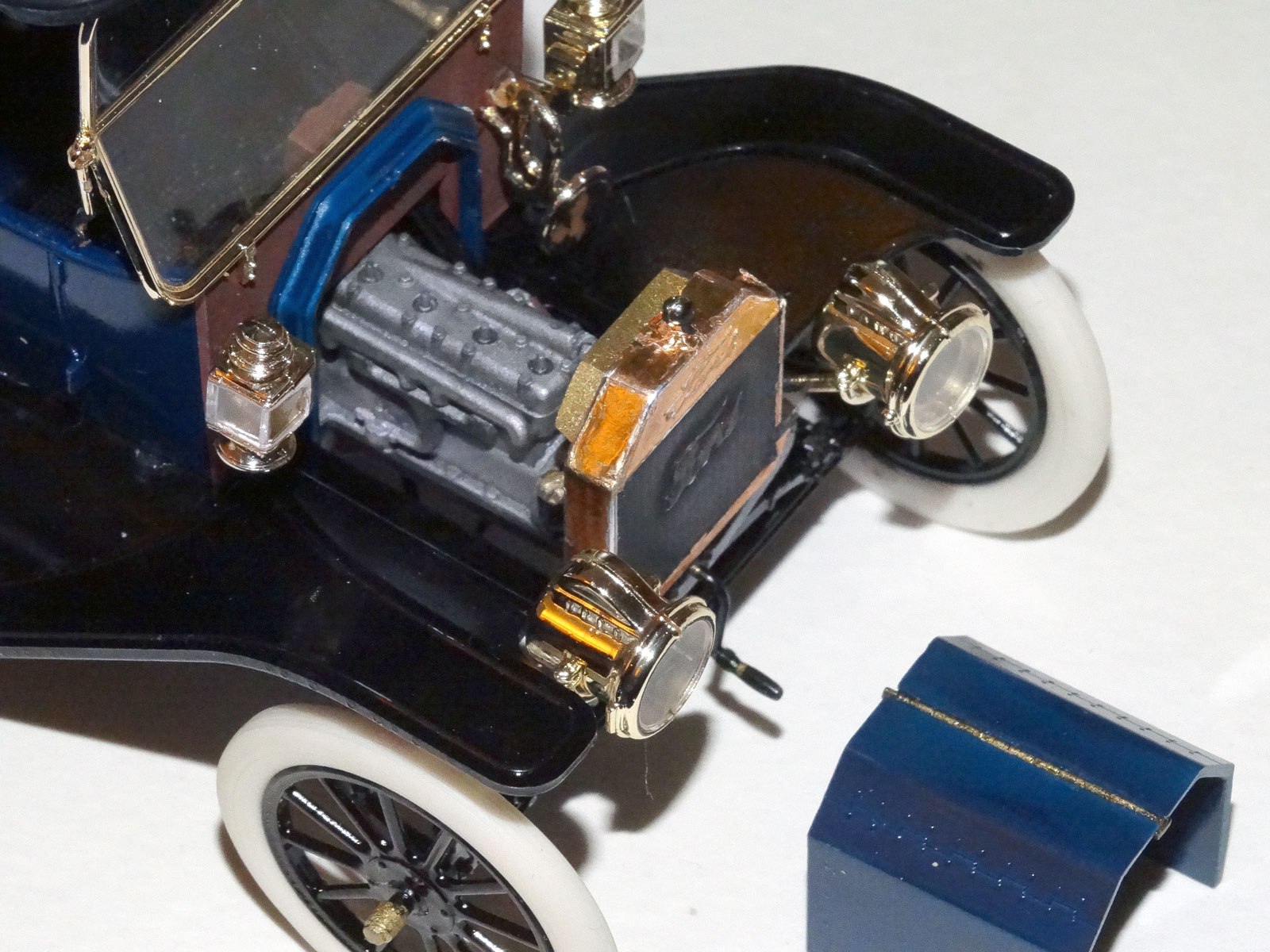
In step 27, you glue the two sides of the hood (B14 and B21) to the hood hinge (B9) that goes between them, and then glue this whole assembly to the chassis, sealing our little 20hp four-banger up forever. But you don’t have to do this if you want the engine to be viewable.
The hood hinge is slightly longer than the hood pieces because the bit that sticks out inserts into the hood-former (part A3) at the rear of the hood. So to make the hood removable, just use the hood-former to get the angle of the hood right by dry-fitting the hood hinge into the hood-former. Glue each hood piece to the hood hinge in the middle, being careful not to glue the hood or hinge to the hood-former. You will have the perfect angle for the hood, and will be able to friction fit it on, or take it off to show off the engine.
By the way, the hinge portion of B9 should be painted in the body paint color. I notice the instructions don’t mention a paint color for the part, and in my build I made it brass, which I now realize is not possible. DOH!
Paint the floorboards (C17) a semi-gloss black, as they would have had a rubber mat on top that had a smooth finish, so it wouldn’t have been as shiny as the frame, but it wouldn’t be matte either. After the floorboards are black, mask around the pedals on the driver’s side of the floor, and paint the area around the pedals brass. I admit that I masked on the outside of the lip around the pedals, but the lip would have been a feature of the rubber mat, not the brass pieces that surround the pedals.
One complaint I do have is with regards to the pedals. The pedals have the flat pedal at one end, and a shaft underneath. It looks just like the real pedal (except for the linkage to the transmission at the end under the floorboard). But because only the shaft goes through the floorboard, there is nothing underneath for the pedal to glue into. When you go to glue the pedals in, you have to glue them to the side of the slot that they “travel” in, so it is easy to get the pedals to not line up precisely. It seems that ICM could make the bottom of the pedal shaft have a bend at the base, so the modeler could fish the bend at the end through the slot in the floorboard, and cement the end of the piece to the bottom of the floorboard.
I could and should have modified the pedals and done this, but I went ahead and tried to glue the pieces in place and used CA accelerator to get them to stick in the right orientation before my hands got jumpy and I ended up gluing the pedal to a finger or my tongue, or my grip with the tweezers gave up and the tiny little pedal found itself glued to the carpet. So the pedals on my car aren’t exactly perfect, but it will do for as much as you can see them.
The horn is an interesting subject. The horn is brass, and glues together in three parts outside of the car, and there is a horn hose on the inside that goes from the firewall to the rubber squeeze ball on the end of the hose. The exterior part of the horn, part D21, has an ugly-looking seam line on the center of the end. “The seam! The brass! What do I do without damaging the brass?” Don’t worry about it – the center of the front of the horn had a screen on it to keep bugs out, so you can just clean up the seam, scraping off the brass as you go, and then hand-paint it acrylic brass, which will maybe simulate it being a screen instead of being solid brass(?).
The tiny little itty bitty part, C10 that helps to hold the horn in place on the outside firewall is not needed. At least you won’t find one on my model. As a matter of fact, I think only the vacuum has a chance at finding that part, if you take my meaning.
In step 52 where you put the headlights into the forks that were added in step 11, just friction-fit the headlights between the forks, if you can. The parts on the original car would have been adjustable, but if this causes you any trouble, go ahead and fix them in place, but remember that you will need an adhesive like white glue that will glue brass-coated parts to other brass-coated parts, and not frost the brass, nor leave noticeable glue blobs in plain sight.
The running lights are very nicely done, and have clear lenses that fit snugly into the light fixtures – so much so that cement is not required. To finish the look, before inserting the lenses into the slots in the running lights, you need to carefully apply brass paint on it on the outside corners of the clear plastic. That will make the lenses look like they are inside the brass fixture. This is documented in the instructions.
Next the top brackets (C11 and C12) are installed in tiny grooves on the back corners of the body. Make sure that they are perpendicular to the front of the car, and that they drop at close to 90 degrees downward as well.
After the brass handles are put on the trunk, the last thing to be added is the Carbide Generator (parts D2 and D3 assembled in step 56). On the real car, the carbide generator would drip water onto calcium carbide, and the resulting acetylene gas would travel up to the headlights. The position on the running board that they provide in the instructions looks good to me – on the running board outside the driver’s door. If that seems inconvenient to the driver, remember that Model Ts made for the US market didn’t have an opening door on the driver’s side from 1913 through 1925, because the location of the hand brake made getting in and out on the left of the car impractical.
Speaking of the hand brake, they cast that in the brass section. I actually believe the whole thing was black on the real T, but without my reference materials I can’t be sure. Since it was already nicely done in brass, I just painted the shaft up to just below the handle gloss black, and kept the nice brass handle. The instructions say to put the hand brake straight up, which on a T technically is in “brake” mode, but anyone parking their Model T would have put the brake lever all the way forward. Because the Model T’s brake lever served two purposes, it was used for an emergency brake when pulled all the way back, when it was in the middle it put the transmission in neutral, and when it was all the way forward, the transmission was in high. So when you parked the car, you would put it into high – all the way forward.
When driving a T, the general approach would have been to:
You can see why I’m not so worried about just anyone stealing my Model T off the street. Even if your Average Joe could manage to get the engine started with the hand crank, they would stall it 7 or 8 times before I waddled up behind them and asked them what the heck they were trying to do, and if I should call the paramedics to splint that broken arm of theirs.
Conclusion
This is a beauty of a kit, and a pleasure to build. There are times when big-old fingers have trouble grasping little-tiny parts, but the end result is a nifty little kit. If you back out the waiting for BareMetal foil and some family “emergencies”, I probably spent somewhere around 15 hours or less on this kit, and I am not speedy in the least. But your results may vary.
A big thank you goes out to IPMS for letting me review this delicious kit, and ICM for designing it, for preserving the history of the Model T in their own way, for giving me the opportunity to build it, for zipping off the new brass parts in the mail in such a hurry, and for being so accommodating with replacement parts in the first place!
I liked this kit so much that I bought a second one, and am playing with either building it straight in another color, or building it as a T that had been stored in a barn in the Midwest for 70 years. It seems such a shame to not build it into its natural glory, but a weather-beaten Model T has so many stories to tell…