
Tips and Tricks
- Basic Modeling Techniques
- General Modeling Techniques
- Advanced Techniques
- Creating realistic Bamboo
- Biplane Rigging Jig Assembly Instructions
- Rigging Instruction Guide
- WWII German Figure Painting Guide
- YouTube Video - Chipping and Chip Types
- A Slick Trick for Drag Slicks
- Airbrushing Armor
- Building an Airbrush Cleaner
- Building an Airbrush Paint Booth
- Airbrushing Using C02
- Keeping it Clean
- Using Filters
- Pigments Revisited
- Wonder Tape
- Working with Photoetch parts
- EXTERNAL SITE REFERENCES
Fine Scale Modeler Magazine Techniques - Cyber Modeler
- Genesis Models
Basic Weathering Series - Modeler Site
- Testors Scale Workshop with Brett Green
- PlasticModels.eu
- Armorama Techniques
- Mig Step-by-Step Series Features
- Dirt and Grease - Mig Jimenez
- Jet Exhaust - Alexander Kutovenko
- Acrylic Washes - Sergiusz Pęczek
- Photoetch tips - Javier López de Anca
- Step-by-Step: Weathered Tank Wagon
- Step-by-Step: How to Paint a BTR 80
- Step-by-Step: How to Use Camouflage Masking Putty
- Step-by-Step: F-16 Fighter USAF
- Step-by-Step: Egyptian M109 2011
- Step-by-Step: Rusted Rails
- Step-by-Step: French Fighter Cover
- Step-by-Step: Colors in the Ukrainian Conflict
- Step-by-Step: How to Use Dry Earth Tracks
- Step-by-Step: How to Use Wet Earth Tracks
- Step-by-Step: World Rally Car
- Step-by-Step: How to Paint a NATO Truck
- Step-by-Step: Making Mud
- Step-by-Step: Finishing Tracks for Armor Projects
- Step-by-Step: French Fighter Cover
- Step-by-Step: Grey Scale - Painting in Modulation and Light
- Step-by-Step: MAXX-PRO
- Step-by-Step: Mud Splashes
- Step-by-Step: Weathering a T-34-85
- Step-by-Step: How to use Transparator
- Step-by-Step: Painting US NAVY F-14
- Step-by-Step: Winter Camouflage Painting - Episode 1 - Slightly Weathered
- Video - How to do streaking rust on a Zaku Lucca 2015
- Video - How to use filters on a Zaku Lucca 2015
- Video - How to make shadows on a Zaku
- Video - How to make Grazes, chips and scratches on a Zaku Lucca 2015
- Video - How to create dirt with pigments on a Zaku
- Video - How to create an accumulated dirt effect on a Zaku
- Video - How to use chipping effect on a Zaku
- Video - How to make Grease and wet effects
- Video - How to make Fading effects with oils
- Video - How to make Splashed dry mud
- Video - Chipping Effect
- Video - How to use Washes and pigments on rust
- Video - How to create winter camouflage mud effect
- Video - How to Create streaking rust on winter camouflage
- Video - Winter camouflage highlights and shadows using oil paints
- Video - Winter camouflage chipping
- Video - Winter camouflage streaking grime
- Video - How to Create highlights with oil paints on winter camouflage
- Video - How to use enamel washes on winter camouflage
- Video - How to Create streaking grime on panels
- Video - How to Create paneling on metal surfaces
- Video - How to Create base rust effects and final touches
- Video - How to use a washable base color
Tips and Tricks
Rigging: Common Modeling Skills Applied
by Scott Kruize
Consider adding rigging to your regular repertoire of modeling skills. This 'how-to' is a review for people who did – and a catch-up source for those who didn't – attend the rigging seminar that followed our October 13th Chapter meeting. The point to make right away: rigging can be done by any modeler, not just those who win 1st-place ribbons and trophies against determined, skilled competition at our Contest-&-Shows. No element of the job of rigging is difficult, or beyond the reach of anyone with normal modeling skills. Rigging IS 'fussy', requiring attention to detail, but that makes it no worse than other tasks: making tight seams, aligning surfaces, painting decent finishes, or making decals lie down nicely over shaped surfaces, without cracking or silvering. In short: rigging is just one more late step in making a decent replica.
Regular readers recall our Vice-Prez doesn't permit me (or anybody?) to talk or write about what I can't do for the Club, only what I can. Recall also he's been willing to organize after-meeting seminars, but hasn't had a host volunteer in a while.
Two buddies that I carpool to meetings with have seen me stretch sprue, but persist in thinking it's slight-of-hand magic, beyond the ability of ordinary humans. The thought occurred maybe other members might benefit from a stretched-sprue demo, so I offered to host one after the August meeting. Eric went along with that, but remarked what he'd really like is a seminar about the basics of rigging.
I'm no master builder, certainly not one to rig biplanes and the like to perfection. But I was an attentive student at a similar seminar Stephen Tontoni taught several years ago after a NorthWest Scale Modelers meeting at the Museum of Flight. He used to say that with each new build, we modelers should 'stretch ourselves', building some new class of model, testing a new paint or other material, or trying some new technique or skill. Before his presentation, I knew little more than that sewing thread could be tied to a strut, wound around another, and another, and finally tied off again. Enough repetitions led to a state of simulated rigging, if a little bit rough and amateurish. I first tried this Way Back When, raiding Mom's sewing box for black thread while building the ancient Aurora Nieuport 28, Lindberg SE-5, and Hawk Nieuport 17.
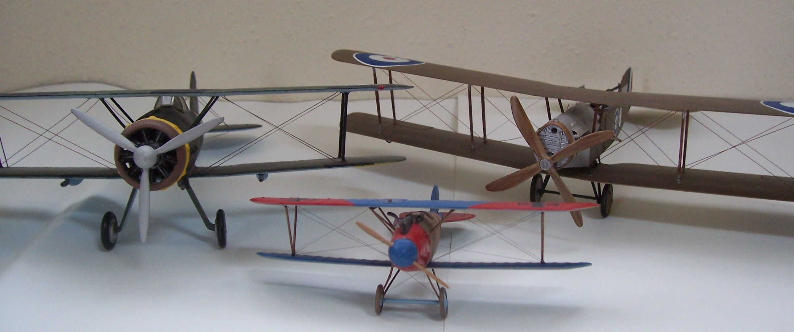
After Stephen's demonstration, I used his techniques on two models thrust upon me by Will Perry, organizer of building model simulations of the Champlin Fighter Collection. Those came out much better than my youthful efforts, even if they didn't make for contest-winning entries. Those current-era-built Sopwith Camel and Fokker D-VII are upstairs in the MOF's Personal Courage Wing's Great War displays. The pic heading this article shows models I've done since: an ancient Inpact Gloster Gladiator and modern-era Roden Bristol Fighter in 1/48th scale, and an even more ancient Airfix Albatros D-Va in 1/72nd.
That led to convincing myself I could at least show fellow IPMS club members what Stephen taught me. I led the seminar at our September meeting, doing the introduction and the first demo work. Further information, refinements, and advanced techniques followed, by Tim Nelson, Jack Matthews, and Ken Murphy. Their rigging skills make for really nice models that HAVE won 1st-place ribbons and trophies against determined, skilled competition at our Contest-&-Shows!
Let me begin as then, reviewing tools and materials. Photos should illustrate:
 Must-have:
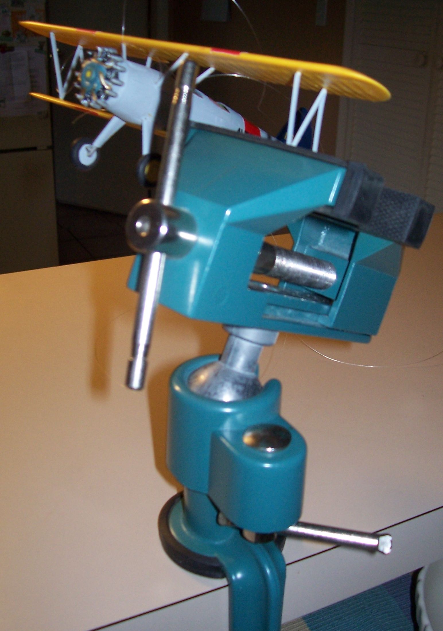
a table-mount vise, ball-and-socket adjustable to permit
its jaws – which MUST be soft-padded – to hold any useful angle, and
be easily changed to any other. Pana-Vise® makes the most elegant, but
usable cheaper ones can be had. Rigging makes me long for octopus
arms... at least a good adjustable vise gives a firm grip on the model
while you manipulate line, glue, and accelerant with your all-too-few
two hands!
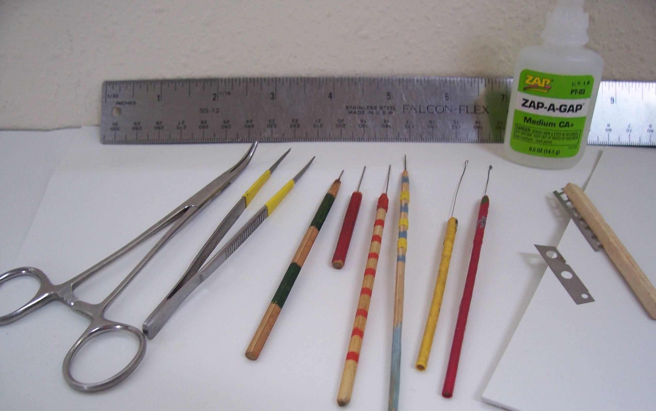
A small set of essential hand tools, shown lined up in this picture. 'Man: the Toolmaker' is a phrase I learned in elementary science class an 'eternity' ago. MicroMark® and other sources make great nifty tools available, but I also make some of my own.
Starting at the left, the first two tools are for holding rigging line. The ordinary tweezers include a slight change: since the blades are embossed for gripping in the middle, I put on some heat-shrink tubing to enable a good grip closer to the tips. Next to the tweezers is a hemostat. I have both straight- and curved-jaw variants, because it's often necessary to clamp and hold an end of the rigging cable.
To anchor any piece of rigging, the minimal need is for a dent in the plastic. You place the line end into it with a bit of CA, and hold it there while placing a tiny droplet of accelerator at the point of contact. A hole all the way through is better: you can gently tension the line where it comes out the hole on the other side, then dab first CA, then accelerant, into the hole from whichever side is easiest. Emphasis from Tim Nelson, a.k.a. RocketMan: “It's all about the hole!” That explains the next set of four small straight probes. The one with green markings is a needle set into a bamboo skewer and sharpened on a fine grindstone. This is my center-punch to locate where I want the drill bit to begin. The drill bits themselves I used to try to twirl in a pin vise, but mine is really too large and awkward for this particular job. I've therefore taken very fine numbered bits, of 20 thousandths diameter, and set them into short, medium, and long skewers.
For drilling plastic parts before starting assembly, I use that short red one, placing the part on scrap plastic or wood, and drilling straight down into or though it. The medium-length one, marked with the red stripes, is for plastic shapes more complex, such as around fuselages. Lastly, the long one marked in blue-and-yellow is used when a hole – or at least a dent – is needed somewhere in a now-assembled model, and can be reached only from an awkward outside position. That's my drill of last resort, but one way or another –I say again, heeding RocketMan's admonition! – you do need at least a dent, and a hole all the way through a part is better.
Stephen rigged with low-test nylon monofilament fishline. I've settled on 4-pound test, which calipers measure out as seven thousandths of an inch in diameter. That's about the smallest I want to handle, and to my eye, looks about right on 1/48th models, my preferred scale. But finer is available, even down to 1 pound test, and would fit better visually on 1/72nd scale models. (But see my colleagues' notes about their preferences using other rigging materials.)
That establishes my drill-bit size: 20 thousandths, large enough to 'easily' poke through a single line of the type I use, and with some frowning and fussing, two. Two rigging runs sometimes need to start from a common point.
Stephen's method – to describe further – is to anchor the ends of the fishline with accelerated superglue. My glue of choice is Zap® Industries Zap-a-Gap® medium-viscosity CA+. There are other good superglues out there, if you stick to those intended for hobby use, not general household repairs. Bob Smith® Industries has a whole line of CAs and all are known to work well. What viscosity to use is something of a matter of personal choice – and I've made mine... thick 'gel'-type leaves large unsightly blobs. Super-thin formulas I have used, but have awful trouble confining small amounts to the places I want it to be, and contrariwise, it's very easy for such glue to run all over the place, especially where it's least wanted. (Voluminous details about this quality of thin CA may be readily sourced from our Former Prez-for-Life Terry Moore...)
Cement for polystyrene has no effect whatsoever on nylon fishline or any other rigging line material I know of... except for stretched sprue, which INSTANTLY dissolves and breaks on contact with even the tiniest drop! –Stick with superglue, 'CA' (cyanoacrylate), and as I've suggested, medium-viscosity should serve best.
A word about accelerating superglues: when doing structural building, I recommend DON'T! The resulting joint is noticeably weaker than an un-accelerated one, where the CA has been allowed to set by itself, in its own time, undisturbed and undiluted. I use an accelerator for two purposes only: one when I'm using CA as a seam- and gap-filler, where I pile it on, force it to set up instantly, and then shape the resulting blob, right away, with wet sanding. As a filler, ultimate strength is unimportant.
The other job I accelerate is rigging, where again, ultimate structural strength is not important. There's very little tension on rigging line, once installed – as long as you treat the model carefully and don't ham-handedly stick your fingers into rigged spaces. None of you would ever make mistakes like that, would you? Especially not when carefully taking your models to Show-and-Tell, the big model display in February at the Museum of Flight, and certainly not on the way to IPMS Contest-&-Shows.
To apply a tiny amount of CA, and an equally tiny amount of accelerant, I made the little yellow and red probes that you see next, in the tool set picture. They're fine-gauge spring steel (music) wire, with a tiny loop bent into the end, the whole anchored into a dowel or bamboo food skewer.
The model gets oriented in the universally-adjustable vise till the line runs slightly downhill to the attachment point (dent or hole) currently being worked. With a drop of CA in it, the loop is placed against the line just up from the dent or hole, and slid the short distance up to it. The CA will wick (move by capillary action) into the dent or hole. Then an equally tiny drop of accelerant is applied with the other probe, in just the same way. As the accelerant wicks in, the CA will set almost instantly, and then the rigging line can be cautiously released.
After a few such glue drops are set, both the loops jam up with accelerated superglue, so an essential tool is a box of matches, or a candle burning nearby. A brief touch of flame burns off the congealed CA instantly.
Over on the right of the tool set picture, a scrap of plastic supports two sharp thingeys. I handle CA by squeezing out a small dollop onto the scrap, then pick up a tiny droplet with my improvised loop-tipped probe. The scrap saves the work surface – in my case, the dining room table – thereby preserving Domestic Tranquility with my Significant Other, wife Sandra.
The sharp things both come from a cheap plastic multi-blade shaving razor. The blades are carefully cut from it and one made into a miniature knife from a scrap of balsa. This I use to trim the excess off a secured rigging line. Even fine craft- or eyebrow scissors, or MicroMark® cutting tweezers, would still leave a protruding stub, which would immediately attract and offend the eye.
The other blade from that taken-apart razor is unmounted. I'll get to its use towards the end of my description of rigging steps.
The following description of procedures is for doing a biplane, but the basics are similar for any model that requires rigging. To start, look over the unassembled – or only partly-assembled – model, and drill dents or holes where the lengths of rigging need to go. [A fully-assembled model CAN be rigged but that's way more fussy, time-consuming, and hassle-y.] Plan first: with care, routes to bridge many runs, from one anchor point or strut to another, will minimize the total number of runs needed for the whole job. Consider that Bristol Fighter. A single run – one length of rigging line – starts at the upper end of the port front outer interplane strut, to the lower end of the front inner interplane strut, then up to the top of the port forward cabane strut, and finally down to the base of the starboard front cabane strut. An analogous long run is made to match on the starboard wing.
After the planning sequence, followed by drilling, the model is then brought to a mostly-assembled state, except that the top wing is left separate. Depending on the model's actual configuration, it's usually best at this point to glue in the ends of some of the rigging lines, at the most hard-to-access dents or holes. In the case of the PT-17 used at the seminar, I glued each of the four lines needed for the major wing rigging into holes drilled inside, at the base of, the four cabane struts, where they enter the upper fuselage decking. Only then was the top wing installed on the struts, and the rigging job continued from there.
One end is glued to a hole or dent, then the line is routed and threaded through as many other anchor points as is feasible. Gently, the line is then pulled taut, and the last hole or dent glued. Surplus line is trimmed off with that improvised razor knife, and the next run tackled.
A seminar attendee wanted to know how long, after one starts work on rigging, each run takes. Would that a precise answer could be given! For myself, doing a World War I or Golden Age biplane of standard design, rigging takes a couple of evenings of effort, a couple of hours each. 'Your mileage may vary!'
The last end to be slipped through and glued might emerge from, say, the top surface of the wing just over where an interplane strut anchors. This is where I again take the lead as 'Man: the Toolmaker', figuring something out that Stephen didn't show at his seminar. You can't leave a cut stub of nylon fishline protruding even slightly out of a plastic surface. However thin the line, however short the stub, it's conspicuous and offends the eye... but you can't sand it flush; you'd only destroy the plastic surface around it. That's where my tool idea comes in... OK, I didn't exactly create it, but did figure out how to use it. It's that unmounted thin cheap razor blade: bent down flat against the surface, a slight sawing motion will cut the line right at the level of the plastic surface. A teensy paint dab and that end disappears.
Faithfully following all these steps, as carefully as possible, likely still leaves you with some sags along some fishline runs. Don't whine, don't throw the model against the wall. Some Total Clever Dick has figured this all out. (I wish I could claim it was me...)
Strike a wooden match, blow it out, and while its head is still warm, wave it near any sag in the line. Not against the line, which will instantly melt through; just near it. (Match must be wooden; paper ones are treated with an anti-smolder chemical, and are uselessly cool even right after being blown out.) My own variation is to use a length of bamboo skewer, a bagful of which I keep handy to mix my paints. If lit and then blown out, it will retain for awhile a tiny glowing ember at the tip, which can be used – again, carefully! – to bring near any sagging lines. These will tighten right up. (But read also of Tim Nelson's approach.)
 That's all I have for now. I repeat: rigging is not difficult, just fussy. It gets easier, and the quality of the work gets better, the more one does it... like everything else, as we model. Those of us who get really skilled augment the techniques described here to incorporate photo-etched simulated turnbuckles at cable-attach points, and even rig closely-doubled-up flying- and landing wires, simulating the actual doubled ones used on 1-to-1-scale planes of the era. But certainly an acceptable rigging job can be done with just Stephen Tontoni's method. Follow his exhortation and try something new. A whole range of subjects you've been avoiding now come into your sphere of possible builds. Regards and encouragement to all!