Reviews
Armor
Bronco Pz. Kpfw. III Ausf. A
by Andrew Birkbeck
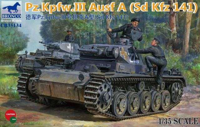 Model: Pz. Kpfw. III Ausf. A
Reviewed by: Andrew Birkbeck, IPMS # 27087
Scale: 1/35
Company: Bronco
Price: $63.99
Product/Stock #: 35134
Website: Dragon
Product Web Page: View
Product provided by: Dragon
Background
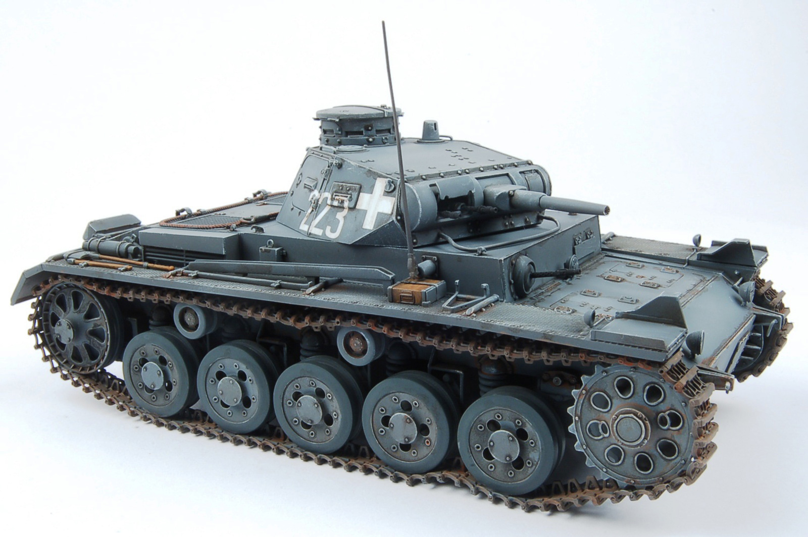
The Panzer III (Pz Kpfw III) was Germany’s first main battle tank, all previous designs being smaller so called “scout” tanks. In early 1934 the German Army, now rearming after the National Socialist (Nazi) takeover of the German national government in 1933, put in motion via the Army Weapons Department plans for a new medium tank weighing 24 tonnes and with a speed of 34 KPH. Daimler-Benz, Krupp, MAN, and Rheinmetall all submitted design proposals and produced prototypes, with Daimler-Benz being awarded a contract for production of the new tank in 1937. The new tank was designated Panzerkampfwagen III Ausf A, and 10 vehicles were completed by the end of the year. Armor on the new tank varied from 5 to 15mm and was designed to protect it from small arms fire and shell shrapnel. The main armament, mounted in a revolving turret, was the 3.7cm Kwk. 36 anti tank gun. Also mounted in the turret were two 7.92mm MG-34 machine guns, with a further machinegun mounted in the front of the hull. Of the ten vehicles produced under the designation Panzer III Ausf A, two were unarmed. Small batches of vehicles under the designation Panzer III Ausf A through D were produced (10 – 15 vehicles per batch) before the first mass produced version of the Panzer III, the Ausf F, started rolling off the assembly lines in 1939. The Panzer III Ausf A is easily recognized by its large five per side road wheels, whereas the Panzer III Ausf B through Ausf D all have much smaller road wheels, 8 per side, before arriving at the mass production versions, which have six road wheels per side. The Panzer III Ausf A vehicles fought in the Battle for Poland in September 1939 before being withdrawn from frontline service.
What's in the Tamiya Box?
- 6 sprues of gray plastic parts
- 3 large gray plastic parts: lower hull, upper turret shell, upper hull unit
- 1 small sprue of clear plastic parts
- 4 small sprues of brown plastic parts (track pins)
- 17 small sprues of brown plastic parts (tracks)
- 1 fret of photo etched brass parts
- 1 sheet of water slide decals with 4 different marking options
- 1 color instruction booklet, 20 pages, with 27 assembly steps
Under Construction
The instructions that come with the kit are typical of Bronco’s range, that is very well laid out and easy to follow. As with every Bronco military vehicle kit I have ever built, this Panzer III kit is loaded down with masses of parts, all very well detailed, and many of the parts are very small, and quite fragile. Care must be taken when removing the parts from the sprues to avoid them being damaged, or flying off into the nether regions of your model room, never to be seen again. The parts are for the most part flash free and mainly free of unsightly ejection pin marks. There were no sink marks experienced on any of the parts. The photo etched brass parts are in some cases so small as to be almost unusable. I will be honest and say that this kit is for the experienced modeler. This isn’t a criticism as it can be in some cases, but simply an honest assessment of the complex nature of this kit, and its numerous small parts. Read on….
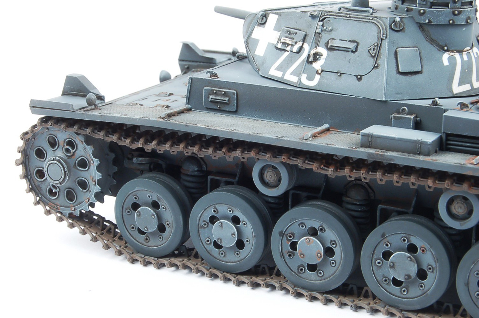
Construction begins as with most armored vehicle models, with the lower hull. Bronco gives the modeler a large one piece hull tub, which has clearly been produced with the latest in slide mold technology. It is extremely well detailed. The road wheel cushioning springs are lovely three part units, and when assembling them, study the assembly instructions carefully, as there is a small pin on the assembly’s base that needs to be facing in the correct direction in order to mate up with the road wheel arms. Note too that the front and rear road wheel arms are different part numbers than the middle three, even though on the instructions they look identical. Don’t mix them up. Use a straight edge ruler to align the ten road wheel arms, five per side.
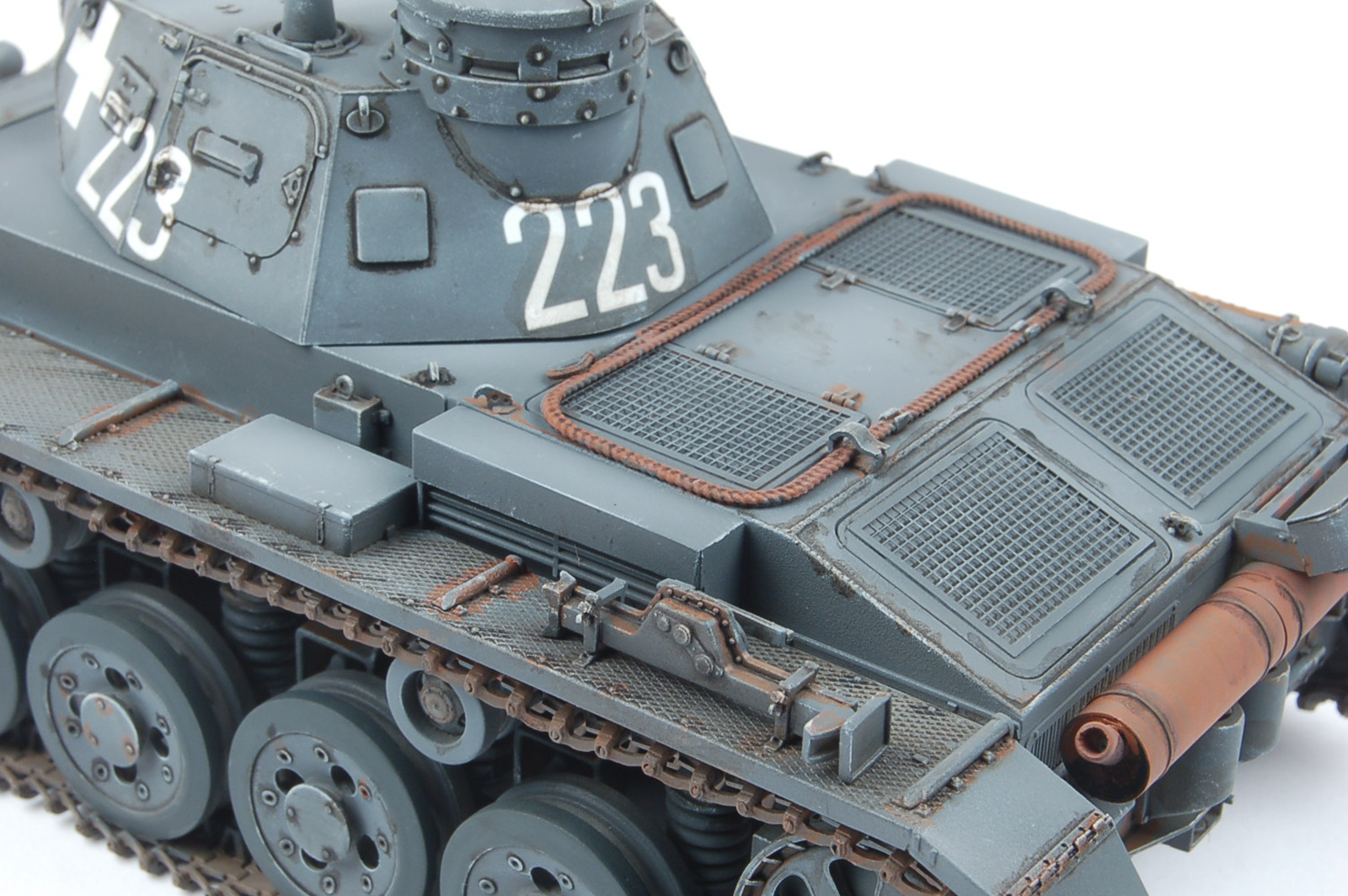
If you examine the main road wheels, parts A62 and A63, you will notice that they have a “step” in the rubber tire section of the wheel. There should NOT be such a step, and it appears Bronco misinterpreted a photo of the Panzer III Ausf A’s road wheels in the book “Panzer Tracts No. 3-1 Panzerkampfwagen III Ausf. A, B, C, und D” by Thomas L. Jentz and Hilary Louis Doyle, page 3-34. What to do about this error? Well, you could always ignore it and move on, but I must admit that not only is this “step” wrong, it also just “looks wrong”. The moment I looked at the wheel parts I said aloud, “wow, what gives?” So for me, leaving them as is wasn’t an option. The next thought was to grind the step off, which would leave the modeler with wheels that were too small, and not enough rubber on the wheels. And the rubber section is quite prominent on the Panzer III Ausf A’s wheels, so this didn’t work for me either. In the end I found some Evergreen plastic strips of the correct width, though slightly on the thick side, and glued these into the “gap” next to the step. Once the glue had set up for a couple of days, I took a sanding stick and sanded down the slight step caused by the height of the Everygreen strip, and evened it out with the step of the Bronco part. This took a little time, but it fixed the issue nicely.
Note that the parts A46 and A45 are small “caps” that are sandwiched between the road wheel halves, parts A62 and A63, as well as between the idler wheel halves, parts A1 and A2. These caps look identical, but they are NOT, so again, don’t mix them up. In Section 7 Bronco has the modeler glue the road wheels, idlers and drive sprockets to the hull sides. This is a delicate operation, as the whole suspension is very much to scale, and the attachment points for the wheels to the suspension arms isn’t that “bulky”. I glued the first and last road wheels to the arms first, and then put them in a little homemade jig to get them lined up nicely. Once these were solidly set up, the middle three road wheels were glued to the arms, and the lower hull put back into the alignment jig. Once this was completed for both sides of the hull, the idler wheels were attached, lined up with a jig, and when set solid, the drive sprockets were attached. No jig required for the sprockets!
The two mufflers that attach to the rear of the lower hull are 5 part units, and drilling out the exhaust pipe, parts B17, will improve the look of things. On the front upper hull plate, part D3, the modeler glues headlights and a siren. I left these parts off until the end of the kit’s assembly to avoid potentially knocking them off. I drilled the mounting holes for the headlights, parts A28, a little deeper so that the posts weren’t glued flush to the main plate. The front hull access hatches are four separate parts, and allow the modeler to position them open or closed. But having them mounted open at this point is rather pointless, as there is no interior detail underneath them. However, should you wish to wait for a potential aftermarket detail set, or scratch build your own, the “open” option exists for you!
“Be careful what you wish for”, as my Mother used to say. Bronco gives the modeler the opportunity to build a fully articulating set of tracks, utilizing individual links, individual track pins, and a handy dandy assembly jig. Many modelers have asked for such detail over the years. Bronco obliges. The jig is made from a vinyl- like plastic which is impervious to my usual Tamiya green top liquid cement. Each track link has three sprue attachment points that if you are very careful with your snipping, won’t have to be cleaned up with file or sandpaper. But the tracks are true to scale, so a bit on the fragile side, and need careful removal from the sprues to avoid damage. THEN the modeler needs to line up the links on the jig, and mount the track pins in such a way that they hold the links together, but without getting too much glue on the pins/tracks so that the modeler ends up with NON-articulating tracks, or worse, tracks glued such that you can’t drape them accurately. And while the instructions say that each side should have 97 to 99 links, I advise that the modeler stop at 94 links for a test fit, and then add one link at a time until they have the correct number of links. And don’t assume that each side is identical! The assembly of the tracks was very tedious, and time consuming, but ultimately fulfilling! For the record, I ended up with one set of tracks on “backwards”. HOWEVER, all was not lost (I had glued them down to the return rollers, drive sprocket, road wheels and idler wheel: they weren’t going to be easily removed and repositioned). Turns out that it wasn’t unheard of for Panzer III tracks to be put on backwards in the field! So I can sleep soundly at night, knowing my model with backward tracks isn’t “wrong”.
There are a lot of fiddly little parts when it comes to the assembly of the fenders. Bronco gives the modeler the option to deploy the front and rear fender “flaps” up or down, and they give you the delicate locking mechanisms in a series of fragile plastic and tiny PE parts. Unfortunately they don’t give the modeler alternatives, i.e. the ability to utilize ALL plastic parts or a mixture of plastic and PE. You have no option but to use the PE parts, which turned out to be a bear to remove and clean up. And being PE, they were flat, when they should have been curved. In the end I opted for the flaps up at the front, and down at the back, and didn’t use the locking mechanisms. So sue me………..
The on board tools for attachment to the fenders are very nicely detailed, and come with latch mechanisms molded on. Not quite to scale, but far easier for the modeler than tiny tiny PE latches IMHO. The vehicle jack comes in 8 delicate and very well detailed parts plus two nicely detailed mounts which are plastic, NOT PE. These latches have tiny plastic wing nuts!
Here you will find the use of some small PE parts for the towing cable holds, plus PE engine screens. Nothing here to concern the modeler who takes their time to read the instructions carefully. Note there are options for the engine louvers, so make sure you don’t mix things up.
Bronco allows for the modeler to mount the hull vision hatches open or closed, utilizing some very tiny PE parts for the hinges. The front hull machine gun is a very well detailed multi part assembly, and there are a number of other detail parts for mounting inside the hull in the area of the machinegun. However, despite these detail parts inside the front of the hull, there is for all intents and purposes no driver or machine gunner station detail parts. The model includes a well detailed folding antenna for the side of the hull. This was left off and painted separately to be installed at the very end of the modeling process, to avoid damage
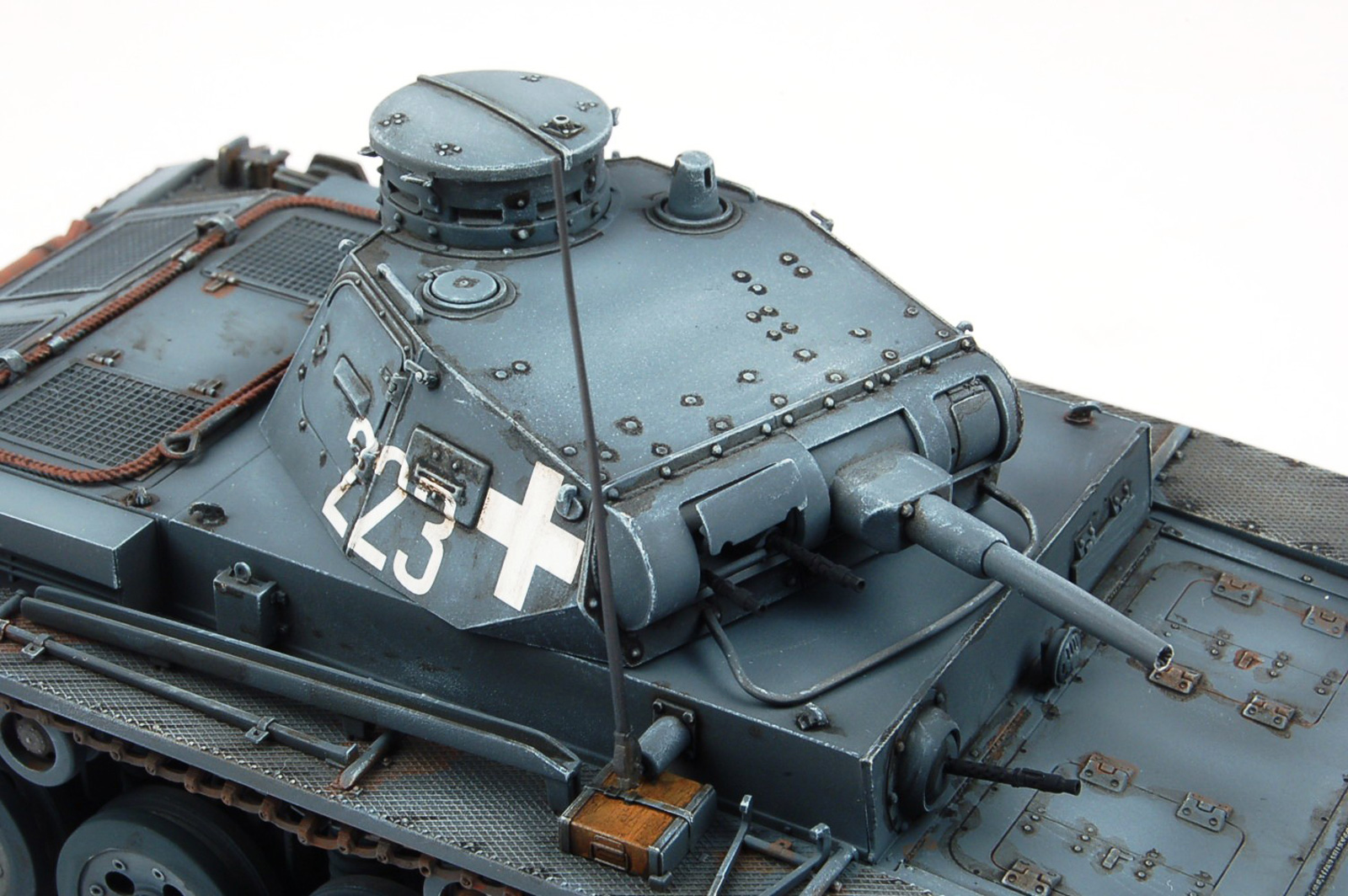
While there isn’t much internal detail in the hull, the turret is another matter. It is festooned with delicate detail both outside and particularly inside. Crew seats, turret ring detail, extremely detailed twin machine gun units, and main gun breech detail is all included: both PE and plastic parts. All the various hatches, both side, front and top have internal and external detail and can be mounted open or closed. I chose to keep the hatch for the twin machine guns open, but closed up the rest. The commander’s cupola is a multi part affair, allowing for the all round vision slots to be mounted open or closed. The main cupola part, J1, is a marvel of slide mold usage, but does have a mold seam line that needs careful removal. Careful study of the instructions allowed me to complete the turret assembly in good order.
Bronco provides the modeler with a small decal sheet covering four schemes. All the vehicle markings are white, and the printing appears to be nicely opaque and the carrier film thin:
-
Option 1: “Unidentified Unit”, Germany, 1938-1939. This option covers a pre-war Panzer Gray and Red Brown color scheme, with minimal vehicle markings.
Option 2: “Unidentified Unit”, Germany, 1939 vehicle “231”. Overall Panzer Gray.
Option 3: “Unidentified Unit”, Germany, 1940. Vehicle has no numbering, simply three small white Balkenkreuz.
Option 4: 1st Battalion, 1st Panzer Regiment, 1st Panzer Division, Battle of Poland, September 1939. Vehicle “223”,
overall Panzer Gray. This is the vehicle I chose to model.
Several light coats of this mixture were applied to the two sub assemblies, and when dry to the touch, I mixed the base color plus more white, and applied a panel preshade. I left the paint to dry overnight, before applying a few light coats of Pledge Floor Care Finish (aka Future acrylic clear) to provide an ultra smooth surface onto which to apply the decals.
The decals were cut from their sheet, and dipped into water, and I must say the decal glue only took about 20 seconds before the decals were easily slid off their backing cardboard. Before applying the decals to the model’s surface, I lay down some of Gunze Sangyo’s Mr Mark Setter, in the blue topped bottle, the milky white compound. Once the decals were in place, and I had mopped up any excess Setter, I let the decals sit for about 10 minutes. Then I applied the more robust of my decal setting solutions, Walthers “Solvaset”. I did this because the decals needed to go over a lot of heavy rivet detail on the turret sides, and I wanted to make sure the decals sucked down like limpets over this detail. After the first application of the Solvaset, I waited five minutes, and then gave each decal another application. After ten minutes, I wicked up any excess Solvaset with small sections of paper towel. I then left the decals to “do their thing” overnight. The next morning, the decals had performed admirably, and for the most part had indeed snuggled down like limpets over the heavy rivet detail. In a couple of areas though I thought they could do a little better. So I applied some more Solvaset onto the offending areas, and let it sit there for about two minutes. I then got a Qtip and dipped one end into the bottle of Solvaset. I gently pressed the damp Qtip vertically down onto the decal, and “pressed” the decal down onto the rivet detail being very careful as I did so to avoid tearing the decal. This all worked like a charm, and after letting the decals dry again over a 24 hour period, they looked great.
I followed up with some more light coats of Future over the decals to seal them. I then mixed up some dark brown/black oil paints in Mona Lisa brand mineral spirits and applied this “wash” to the model to pick out the detail on the model’s surface. After 24 hours, I then took Qtips dipped in Mona Lisa thinner, and whipped away any excess “wash”. When I was happy that things looked decent, I left the model to dry for 48 hours. I then airbrushed a number of thin coats of my new favorite “dull cote”: AK Interactive AK183 acrylic “Ultra Matt Varnish”. If you want the matt-est matt finish around using an acrylic, THIS is the stuff. I didn’t have any AK Interactive thinner on hand, so I used Vallejo’s Airbrush Thinner 71.161, and it worked just fine.
Following this, I picked up a suitable “Wood” color from Vallejo’s acrylic range (they have a couple in the line, “new wood”, “old wood” etc) and carefully painted the on board tool wooden handles. Once thoroughly dry, I then applied some Vallejo “Smoke” color over the wood, which gives a very nice effect. Once dry, a few mist coats of “Ultra Matt Varnish” were applied to the tools. Then I got out my container of Uschi “Metal Polishing Powder” Steel Type. This is as the title implies a very fine gun metal colored power, which I apply to machine gun barrels to give them that shiny look. You paint the machine gun barrel matt black, and then rub the powder onto the black areas using your finger tip once the paint is thoroughly dry. Lastly I mounted the hull side radio antenna.
Conclusion
Overall this is a superb kit, with tons of finely molded detail. Thanks to the easy to follow instruction booklet, I did not experience any difficulties assembling the parts. But due to the large number of these parts, and the fact that many of them are very delicate, I would only recommend this kit to someone who has a good number of armor kits already under their belt. Lovely as it is, this to my mind is NOT a kit for the beginning modeler. But it does assemble into an intricately detailed scale model that will look great in your display case! My sincere thanks to DragonUSA for supplying IPMS USA with this review sample.
Photos