Reviews
Armor
M109A3/M185A3 2.5 Ton 6x6 Shop Van
by David Dodge
 Model: M109A3/M185A3 2.5 Ton 6x6 Shop Van
Reviewed by: David Dodge, IPMS # 49795
Scale: 1/35
Company: AFV
Price: $50-60
Product/Stock #: 35304
Website: AFV
Product Web Page: View
Product provided by: AFV
Intro
AFV Club released this kit in the fall of last year. This is a variant of their M35x series of 2.5 ton trucks of which the M49A2c 1200 Gallon Fuel truck and the venerable M35A2/3 “Deuce and a half” truck was released.
Background
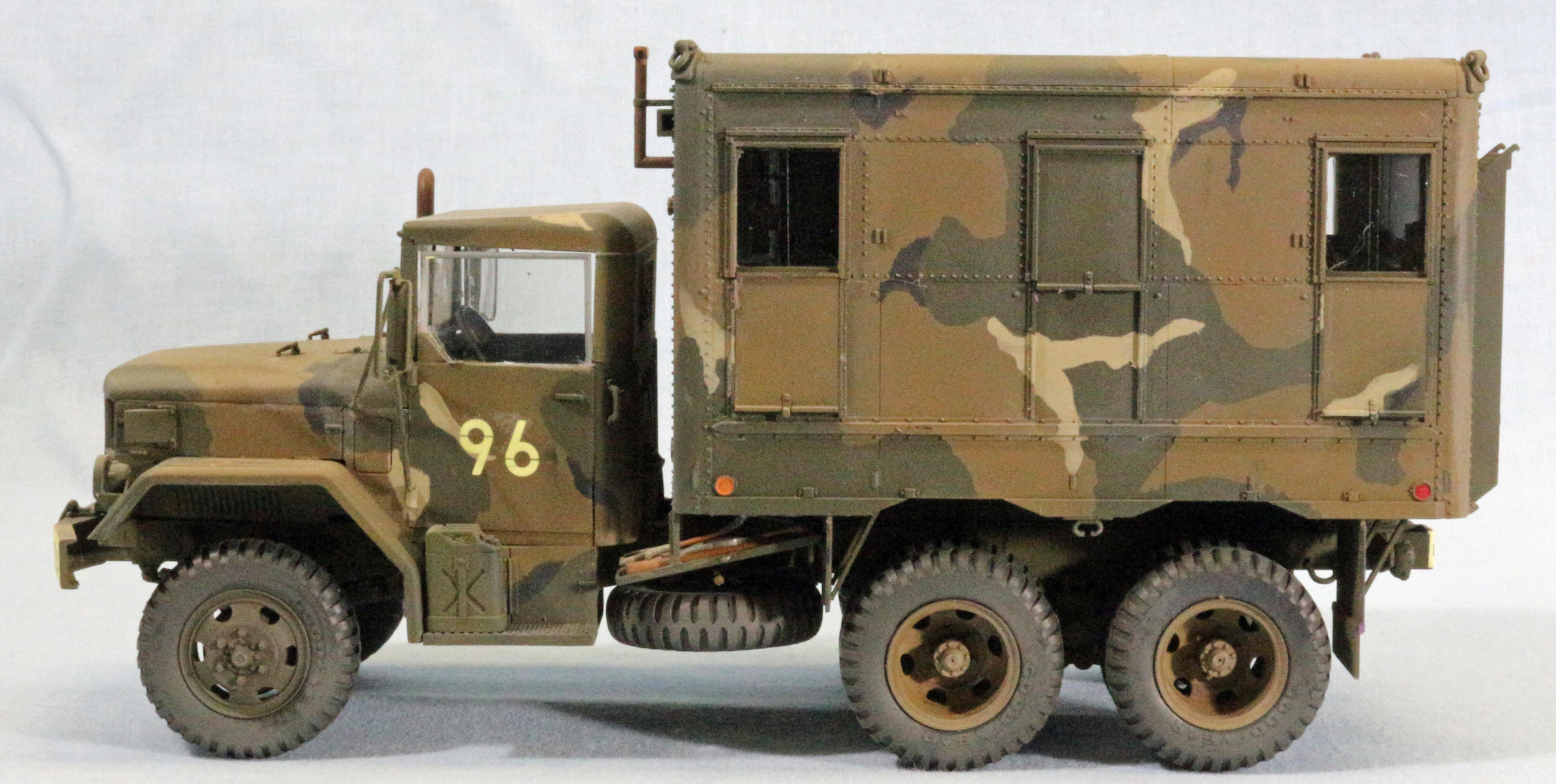
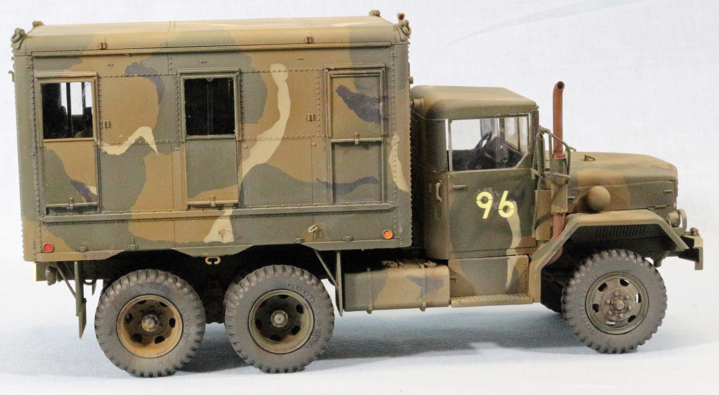
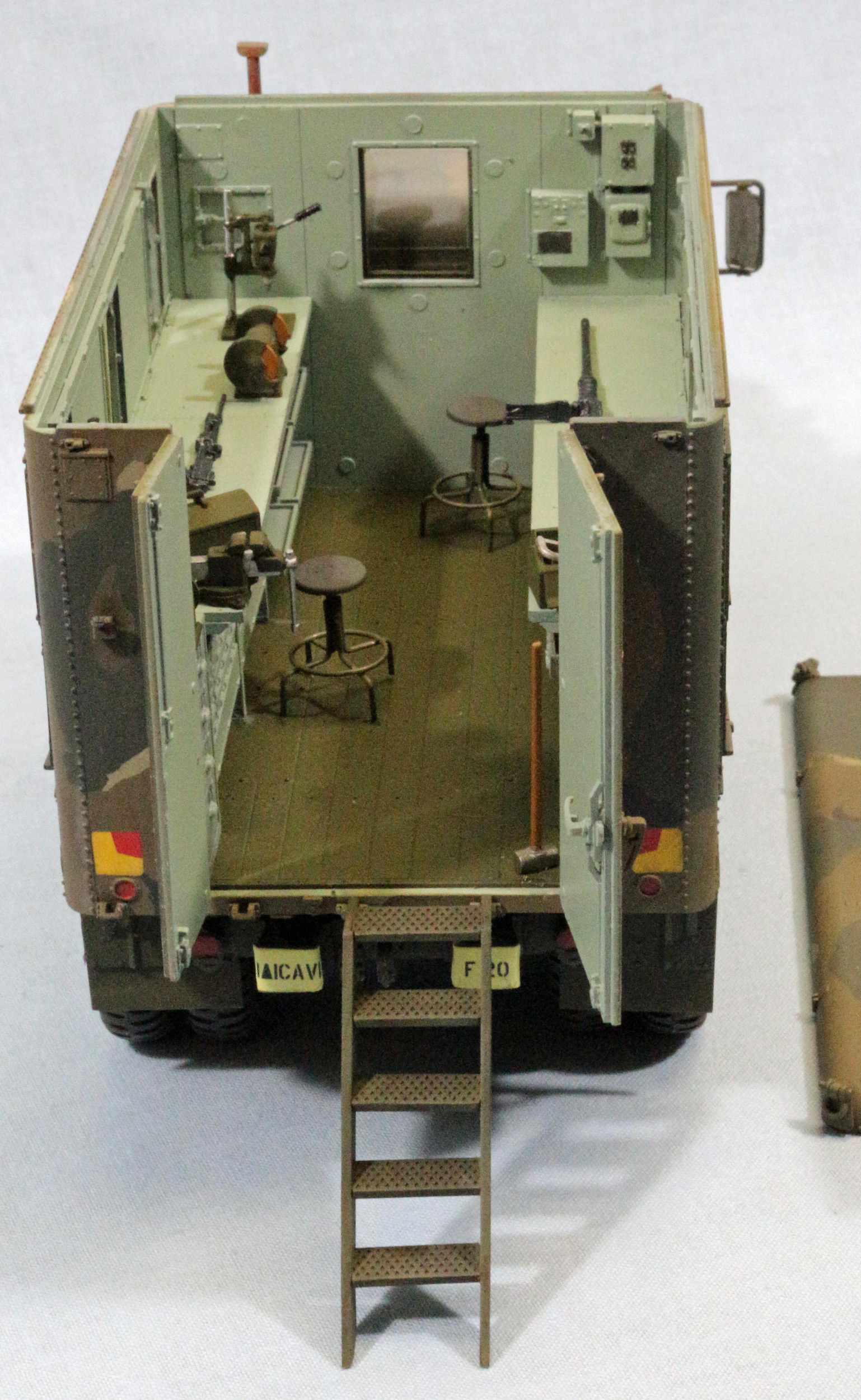
The M35 series of vehicles were derived from the classic CCKW truck from WWII. These vehicles were ubiquitous and were given great credit for winning the war on the logistics front. The M35 was a dual rear wheeled variant of the single wheel 6x6 M34 (which had better off road mobility) and was principally designed for on road use. It was produced initially in the early 1950’s by Rio Motors and was first deployed with a gasoline engine, and in the late 50’s, with a 427 cubic inch straight 6 multifuel engine. This could burn gasoline, diesel, kerosene and jet fuel or any combination. The engine was upgraded on the M35A2 series of vehicles by a 478 cu. in. multifuel engine. This engine was upgraded to the turbo-supercharged engine. This was the most numerous version of this series. The 1949 Rio Motors Design has been produced by over 10 companies including Rio Motors, Studebaker, Studebaker-Packard, Curtis-Wright, Kaiser-Jeep and AM General. The M35 Series of chassis was the baseline for subsequent variants of which the M109A3 was one of those. The M109 has a 12 foot van body that was mounted on subsills to raise it up off of the frame to clear the wheels without housings. The rear of the body has two hinged doors. The left was locked and could only be opened from the inside and the right door had a padlockable latch. There were ladders to gain access to the inside of the van and the roof top. The body has side windows with screens and blackout curtains. Power was provided by the vehicle 24 volt system and external 115 volt AC to run lighting, accessories and tools. The van body was waterproofed to the 8 foot depth line for fording. The van could be equipped with various shop sets to support its use for automotive, electric/electronic or small arms repair.
Opening the box
There are 11 separately bagged OD green sprues a clear sprue three PE frets in two bags, a decal sheet and string and chain for the winch. There are two OD sprues of 12 wheels. 11 polymer tires are on their own sprues. There are some extra parts since this kit seems to be based on the M49A2c Fuel truck. Most of the parts are crisp and detailed with some flash and many of the van body parts have raised or sunken ejector marks that have to either be filled or sanded.
The Instructions
There are 20 pages of instructions. The first and last 8 pages are printed on glossy surface paper, the middle 4 are on standard paper. The color plates are on pages 16 thru 20. There is a sprue map on page 15 that has photos and line drawings of the sprue layout and the decal sheet is a photo. The line drawings have the part numbers, but the three sprues that are photographs, do not.
Things to consider before building
- The assembly of the chassis frame and suspension is not difficult until you get to connect the two frames together. All the frame cross members are attached to one side and in step #3 they are joined, and it makes aligning the rear suspension and differentials tricky as well as keeping it straight. You will have to pay attention and proceed slow, and expect to take time lining everything up.
- Take your time putting in the transfer case (assembly D in step2) and the driveline (A74) to the rear differential. Mine ended up being 1mm too short. Then the trouble began. I had issues from the transmission to the rear differentials. Nothing aligned, the shafts were either too long or too short. To be honest, I wasn’t paying close enough attention and should have test fitted with white glue to check fit all down the line. My initial impression was to blame the kit, but I just can’t at this point do that because it may have been my assembly process flow.
- The kit has a bunch of extra parts for the Fuel tanker, but some parts are needed. Scrub the instructions and then set the sprues aside.
- The Van Body actually goes together pretty well. I had no issues with the entire van build. In fact, I got the top section to actually friction fit so I can remove it for displaying the inside. The kit of tools and power equipment are kits unto themselves. The stools are composed of 5 parts that are VERY delicate, as are most of the tools but look good once removed from the sprues. Be cautions here so you don’t lose or break anything.
The Build
Frame, Suspension and Powertrain and Cab
- Steps One thru eight are the essential steps that get everything together so you can mount the van body. Sub-Steps A, B, and C have multiple units built for both the front and rear drive train components (driveline and differentials)
- Step 1 assembles the frame rails, cross members and lifting lugs to the frame rails. This goes pretty straightforward. Step 2C has the main suspension springs and hangar brackets being assembled to Part C10 (LS frame Rail) from Step 1. Part No A37 needs to be fit filed as it doesn’t sit correctly on the end of the spring and will not mate correctly with the axel assemblies built in Sub Step B. Be fussy here and test fit and check alignment as this helps to locate the front and rear axles along with the links that locate the suspension.
- Step 3 is where the transfer case (Sub-step D) and the frame rails get connected. I knew I had problems brewing once I tried to connect the Transfer case to the front rear differential. It was 1mm too short. I figured I could lengthen it later, so I moved on. The right side linkages and the main suspension spring (Sub-step C) are not yet installed so I moved on to that. With some manipulation, I got the links in and the springs connected to all the right places. Next, the front suspension and axel. Everything fit well but connecting parts A66, 67, and A45 require a bit of study and some careful application of force to get it all connected. The CV joints/Brake assemblies (A66, 67) are press fitted over the ends of the axel and then pivot on the end of the axel. A45 links them together so they turn in tandem. Youi will have to use force to get them in place and they sort of snap in and then swivel. Do each separately and then connect them with A45. The steering linkage (Sub-step E) was a bit hard to figure4 out but there are locators to attach it to the frame and axel.
- Step 4 is where you attach the rear frame parts like the rear bumperettes, stop lights and shackles and pintle. Easy stuff, just make sure it’s aligned so it looks straight.
- Step 5 is tire assembly and attachment. I assembled the rear bogies and painted them Model Master Dark Green (FS079) and Field Drab (FS30118) according to the paint scheme I was using. I left the tires off and degreased them and used Mission Models NATO Black (MMP-035) for primer. I used Mission Models Tire Black (MMP-040) for the color coat. I did not attach the wheels and tires at this point. Since the actual points that the wheels were attached were not real robust for the front and I wanted to get a green coat on everything and didn’t want to mask. The spare tire ratchet shaft (A5) was pretty delicate and I left it off for later attachment. I took the transmission (Sub-step H) and mounted it and tried to attach the driveshaft (A68) and it was too long, another driveshaft length issue. I cut some sprue and fitted it between since this was not going to be an area easily visible. Then move on to Step 6.
- Here I simplified the build and went with a version without the front winch (more drivelines, Yikes!). I then glued the fender assembly onto the frame and moved to the cab assembly. When test fitting the cab onto the frame, it would not align to the frame and it wouldn’t fit cleanly to the fenders. It was obvious something was interfering with a clean fit. (See photo M109A3 P1) Now I had to drop back and punt. I took off the parking brake from the transfer case and that didn’t’ affect the fit, then came out the transmission and transfer case. The cab now fit quite nicely, so I glued it down and aligned everything. Then began Operation Refit. I coaxed the transfer case back into position and was able to get the front driveline top go from the front axle to the transfer case. I was then able to connect the rear driveline after removing a slice. It was now too long instead of too short, but that was easy to fix. I was successful with coaxing and cajoling the transmission back into place. A bit more difficult than the transfer case since it had to skirt all the front axle and steering gear. Added the driveshaft to the transfer case and called it good. The radiator and grille were added and the PE attached (all flat fit, Yeah!).
- The Dashboard is attached to the hood and glued down as an assembly. The dash has 13 decals which added some color to the dash. So I painted the dash dark green, future’d it and then applied the decals. In trying the hood fit to the engine compartment side panels, there was a .010 gap that I used some sheet strip to fill, it doesn’t completely fill it, but reduces it enough to make it trivial. Then glued the hood. On the hood, the directions show part B34 attached to the passenger side. This is the exhaust bracket that is important later. I held off since there were no locator clues, other than a notch. I applied this after fitting the exhaust pipe to see if I needed to modify it for locating the exhaust.
- This is the front detail completion. The windshield fits onto the dash and hood assembly. It fits but there are no positive location like tabs, so it’s a butt joint. Use Testors black bottle liquid cement to get a good bond. Once on, leave it alone and check for alignment. This won’t be stable until you glue the canvas or hard top to the cab. A challenge is the side windows. Once the top is on, the windows have nothing to hold on to. They glue to the door top and the cab or canvas does not hold it. There is a significant gap. So I applied Tamiya masking tape and sealed the edges closing off the cab interior since it was already finished. I attached the PE heat shield to the upper exhaust stack. It mated to the lower very nicely and then attached B34 and B20 to support the exhaust better. The only challenge in this step was the mirrors. There are three parts to each mirror assembly. The driver’s side goes on ok, but the passenger’s side is a bugger. Part C41 curves around the exhaust stack but the end that joins the body is too short, and the attach points on the mirror frame are very delicate and it took quite a bit of time to get the glue to hold anything while trying not to move it around. I ended up having to glue a scrap plastic piece to create a platform for the frame end to attach to. There are no alignment points for the body side of the frame so I used the door hinge tops as the mounting point which worked well for both sides. Note: Part L18, an air scoop on the left front of the engine side wall is also called out in step 15 on the van body. But there is only one L sprue and only one L18 part. I used it on the engine compartment and substituted L19 for L18 in step 15. Doh!
Van Body Assembly
- Step 9 starts the van body assembly process. It starts with 4 workbenches, and two file cabinets. Two benches have parts drawers and two that are shelves. The shelf and parts shelves have horizontal supports for the top. The longer one goes to the top of the workbench the more narrow one goes to the floor. Don’t ask how I know that. I made a decision to fully equip the interior which meant I had to paint everything inside first, which I did, but I decided to assemble the guts after the shell was assembled, so I had a mini shop laying on the workbench for a while until I got it all assembled. I painted the floor top and bottom since it was also the bottom of the truck. The interior sides and top were painted A. Mig -082 US APC Interior Green. The dreaded “Seafoam Green”. There are some components that need to attached to the sides and end walls so I did that before spraying the interior since once assembled, it would be bugger to get to all the corners. The same goes for the exterior doors L12 and L13. I started by gluing the front to the left side to create a corner and then glued the floor into place to create a stronger structure to assemble the rest on. It all went together very well. The joints are butt joints with some alignment between the floor and sides. I press fitted the back doors into the hinge portions on the outer back wall and it all friction fitted nicely and helped the glue to set with everything in place. To check everything I put the roof on and almost didn’t get it off. The fit was that tight, and still is after painting and manipulating to get the stuff placed inside. Well done AFV club. The windows (H1, H2) are a tight fit and require only a little bit of liquid cement. Tamiya green top sparingly gets them in and solid. I masked the outside of the windows since I didn’t want any paint to mark them. There is a vertical bar (I14) that goes on the interior over the center of the windows, don’t forget to paint those.
- Parts L10 and L17 are blackout shields that slide over the windows to allow work during darkness. I used Humbrol liquid mask to attach these to the window masking so they would have the vehicle camouflage pattern in the up position. PE Part GC8 (12 ea) are attachment hooks for ropes or tie downs and are actually made from bent steel rod, but the flat PE part after being bent are hard to attach and get caught on just about everything. They look oversize. I tried to get them all attached but lost a few before they got cemented in place. Several popped off during painting. I would recommend you just leave them off. Note: all the interior walls and top has raised ejector marks that would be hard to correct, not impossible, but time consuming without the right equipment. I chose to leave them alone. You may want to go an extra step. I had fun building all the tools and benches and placing them. I made the shop repair small arms by having some extra machine guns on the benches for repair. The interior accoutrements are delicate and require finesse but you will be rewarded by a nice kit.
Painting and Finish
- I chose one of the 5 color schemes that had a European unit, 1st Cavalry Regiment, 1st Armored Div. This has the late 70s MERDEC Verdant Winter Scheme. This is a 4 color scheme with Field Green and Field Drab that covers 90% of the vehicle and Sand and Black that cover the remaining 10%. This was developed to save paint and time to prepare vehicles as they deploy to different climates by changing one or two colors. It was superseded by the 3 color NATO scheme used now. Once the vehicle was fully assembled, I completely sprayed it the FS34019 Field Green. I didn’t prime it since Model Master Enamels bite pretty well. I then masked the green pattern with Humbrol liquid mask and then shot the Field Drab FS30118 over the rest of the vehicle. The Sand FS30277 accents were masked and sprayed. The Flat Black FS 37038 was then shot as the final color. I removed the masking and touch up painted the hits and misses to clean up the transitions. I then detailed the turn signals and reflectors. Next was the overall Future coat to prep the decal areas.
- There were not a lot of decals, the front and rear unit bumper markings and the vehicle numbers. The Military weight class placard on the front grill, the door number markings and the slow moving vehicle reflectors in the rear. Once the decals dried overnight I spot applied Future over the markings and got ready for some weathering.
Weathering
- I tried to give a somewhat worn and faded paint appearance, but not sure how effective it ended up. I used AK NATO Tank Wash to give some rain streaking along with some Windsor-Newton Burnt Sienna Oils diluted for streaking and staining on the fuel tank and some oil staining around the vehicle. I generally don’t like to overdo it. Once that was done, I applied a dust coat using Vallejo Light Brown (71-027). I may have overdone this step. Then did a final coat of Vallejo Flat Matt varnish to tone down the shine,
- I did other touch ups and tweaks as a final look over, like forgotten masking, and parts, like the spare tire ratchet shaft. You know how that goes, during cleanup you find things.
Conclusion
Despite powertrain and driveline issues, I was able to get everything into a resemblance of a truck undersides. Not sure what the issues really were, but I do have a M35A2 kit from AFV Club that will get more scrutiny when I build that kit. The cab and cab interior fit well but the side windows were a bit wonky. No real good way to attach them. The van body was detailed and extensive but everything fit well together. The hand and power tools certainly fill the benches and could offer opportunities for a diorama. The kit builds up into a nice slightly unusual subject since the stuff that lives way back behind the front lines hardly gets any attention from manufacturers. Most maintenance 2 ½ trucks want to be an M109 van when they grow up.
I would like to thank AFV Club for providing this kit for review, and to IPMS USA for giving me the opportunity to review it.